
How to Use Header 4: Examples, Pinouts, and Specs
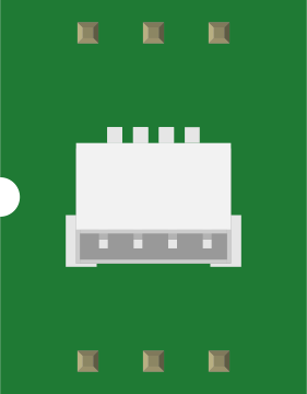
 Design with Header 4 in Cirkit Designer
Introduction
A Header 4 is a type of connector used in electronic circuits, typically featuring four pins for connecting various components or devices. It is widely used in prototyping, development boards, and modular electronic systems due to its simplicity and versatility. The Header 4 allows for easy assembly and disassembly, making it ideal for applications where frequent connections and disconnections are required.
Explore Projects Built with Header 4
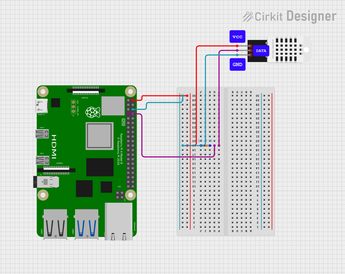 Open Project in Cirkit Designer
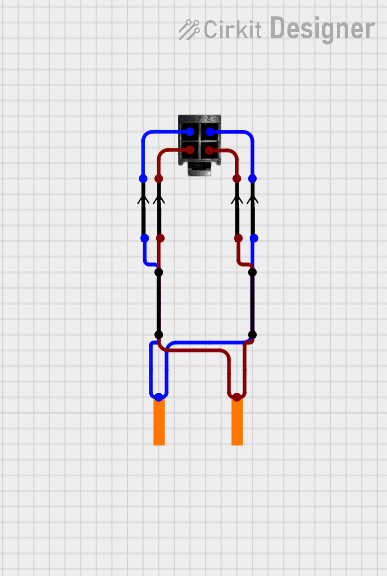 Open Project in Cirkit Designer
 Open Project in Cirkit Designer
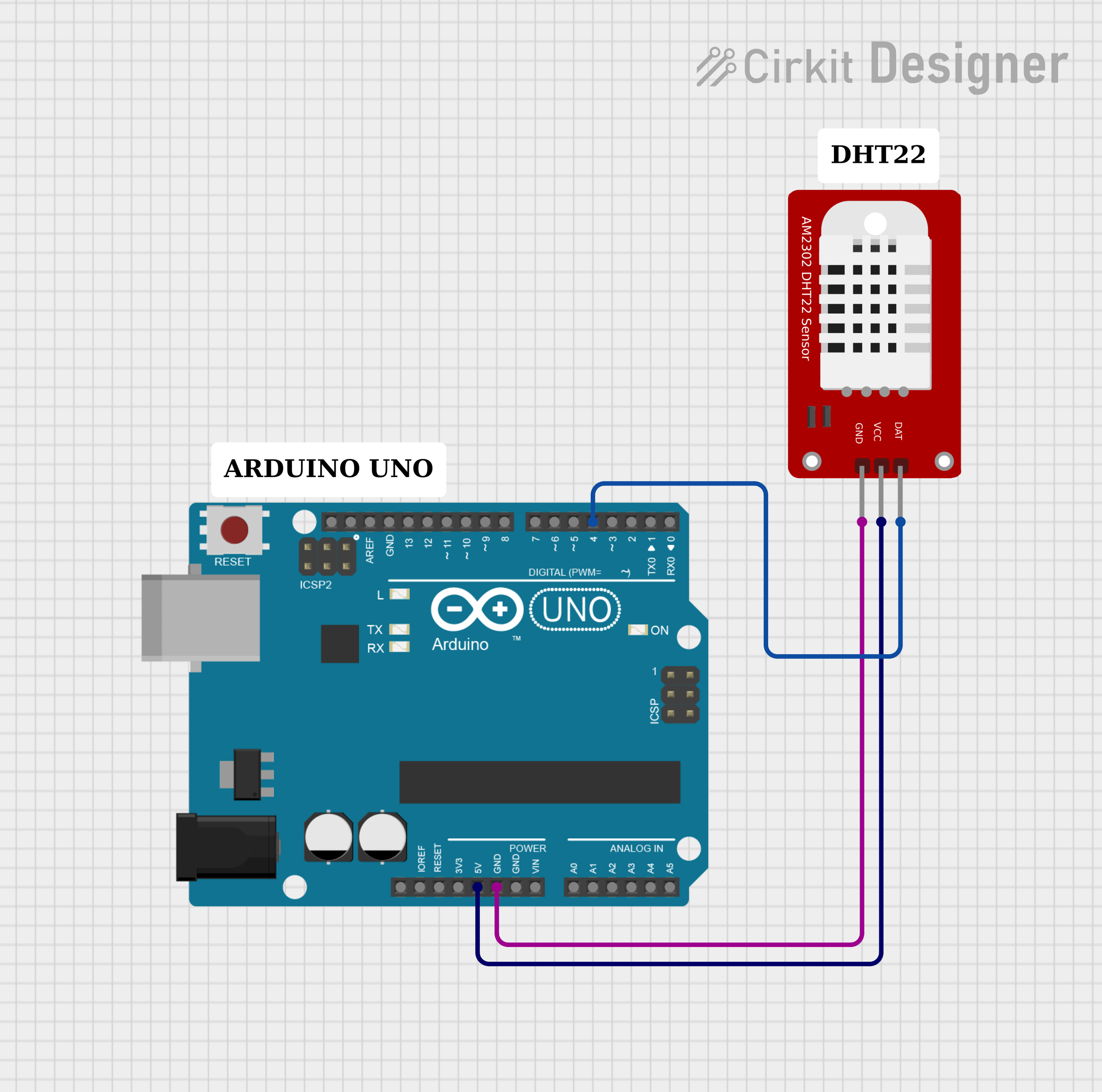 Open Project in Cirkit Designer
Explore Projects Built with Header 4
Open Project in Cirkit DesignerOpen Project in Cirkit DesignerOpen Project in Cirkit DesignerOpen Project in Cirkit DesignerCommon Applications
- Connecting sensors, modules, or peripherals to microcontrollers
- Prototyping and breadboarding circuits
- Modular PCB designs
- Interfacing with development boards like Arduino, Raspberry Pi, and others
Technical Specifications
Key Technical Details
- Number of Pins: 4
- Pin Spacing (Pitch): 2.54 mm (0.1 inch) standard
- Current Rating: Typically up to 3A per pin (varies by manufacturer)
- Voltage Rating: Typically up to 250V (varies by manufacturer)
- Material:
- Pins: Tin-plated or gold-plated copper
- Housing: Plastic (e.g., nylon or polyamide)
- Operating Temperature: -40°C to +105°C (varies by manufacturer)
- Mounting Type: Through-hole or surface-mount
Pin Configuration and Descriptions
The Header 4 connector consists of four pins arranged in a single row. The pin configuration is generic and can vary depending on the application. Below is an example of a typical pinout when used with an Arduino UNO:
| Pin Number | Description | Example Use Case |
|---|---|---|
| 1 | VCC (Power Supply) | Supplies power to the connected device |
| 2 | GND (Ground) | Common ground for the circuit |
| 3 | Signal/Data Line 1 | Transmits data or control signals |
| 4 | Signal/Data Line 2 | Transmits data or control signals |
Note: The pin assignments may vary depending on the specific application or circuit design. Always refer to the schematic or datasheet for your project.
Usage Instructions
How to Use the Header 4 in a Circuit
- Mounting the Header:
- For through-hole headers, insert the pins into the PCB holes and solder them securely.
- For surface-mount headers, align the pins with the PCB pads and solder them using reflow or hand-soldering techniques.
- Connecting Components:
- Use jumper wires, ribbon cables, or female connectors to connect devices to the Header 4.
- Ensure proper alignment of the pins to avoid incorrect connections.
- Power and Signal Routing:
- Assign the pins for power, ground, and signal lines as per your circuit design.
- Double-check the connections to prevent short circuits or incorrect wiring.
Important Considerations and Best Practices
- Pin Alignment: Ensure that the pins are aligned correctly with the mating connector to avoid damage.
- Current and Voltage Ratings: Do not exceed the specified current and voltage ratings to prevent overheating or failure.
- Soldering: Use appropriate soldering techniques to ensure reliable connections without cold joints.
- Strain Relief: If the header is subject to frequent connections/disconnections, consider using strain relief mechanisms to reduce wear and tear.
Example: Using Header 4 with Arduino UNO
Below is an example of how to connect a Header 4 to an Arduino UNO for interfacing with a sensor:
Circuit Diagram
- Pin 1 (VCC) → Arduino 5V
- Pin 2 (GND) → Arduino GND
- Pin 3 (Signal 1) → Arduino Digital Pin 2
- Pin 4 (Signal 2) → Arduino Digital Pin 3
Arduino Code
// Example code for reading data from a sensor connected via Header 4

const int signalPin1 = 2; // Signal pin 1 connected to Digital Pin 2
const int signalPin2 = 3; // Signal pin 2 connected to Digital Pin 3

void setup() {
  pinMode(signalPin1, INPUT); // Set Signal Pin 1 as input
  pinMode(signalPin2, INPUT); // Set Signal Pin 2 as input
  Serial.begin(9600);         // Initialize serial communication
}

void loop() {
  int value1 = digitalRead(signalPin1); // Read data from Signal Pin 1
  int value2 = digitalRead(signalPin2); // Read data from Signal Pin 2

  // Print the values to the Serial Monitor
  Serial.print("Signal 1: ");
  Serial.println(value1);
  Serial.print("Signal 2: ");
  Serial.println(value2);

  delay(500); // Wait for 500ms before the next reading
}
Tip: Use appropriate pull-up or pull-down resistors if required by the connected device.
Troubleshooting and FAQs
Common Issues
Loose Connections:
- Problem: The header pins are not making proper contact with the mating connector.
- Solution: Ensure the connectors are fully seated and check for bent or damaged pins.
Incorrect Pin Assignments:
- Problem: The circuit does not function as expected due to incorrect wiring.
- Solution: Double-check the pin assignments and refer to the schematic.
Overheating:
- Problem: The header or connected components become hot during operation.
- Solution: Verify that the current and voltage ratings are not exceeded.
Cold Solder Joints:
- Problem: Intermittent or unreliable connections.
- Solution: Re-solder the joints using proper soldering techniques.
FAQs
Q1: Can I use a Header 4 for high-frequency signals?
A1: Yes, but ensure that the header and PCB layout are designed to minimize signal integrity issues such as crosstalk and impedance mismatch.
Q2: Are there different types of Header 4 connectors?
A2: Yes, Header 4 connectors are available in various configurations, including straight, right-angle, male, and female types.
Q3: How do I prevent accidental disconnections?
A3: Use locking connectors or secure the connection with adhesive or cable ties if necessary.
Q4: Can I use a Header 4 with a breadboard?
A4: Yes, male Header 4 connectors are compatible with standard breadboards with 2.54 mm pitch.
By following this documentation, you can effectively use the Header 4 connector in your electronic projects.