How to Use 2 gang socket with wire: Examples, Pinouts, and Specs
Introduction
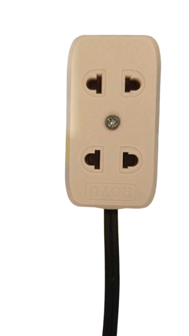
A 2 gang socket with wire is an electrical outlet designed to accommodate two devices simultaneously. It features two power outlets and comes with a pre-attached wire for straightforward installation. This component is widely used in residential, commercial, and industrial environments to provide power to various appliances and equipment. Its pre-wired design simplifies the installation process, making it a convenient choice for electricians and DIY enthusiasts alike.
Explore Projects Built with 2 gang socket with wire

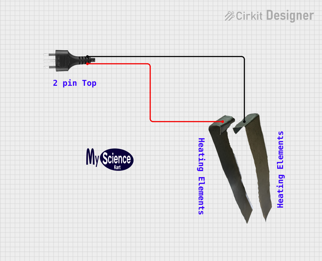

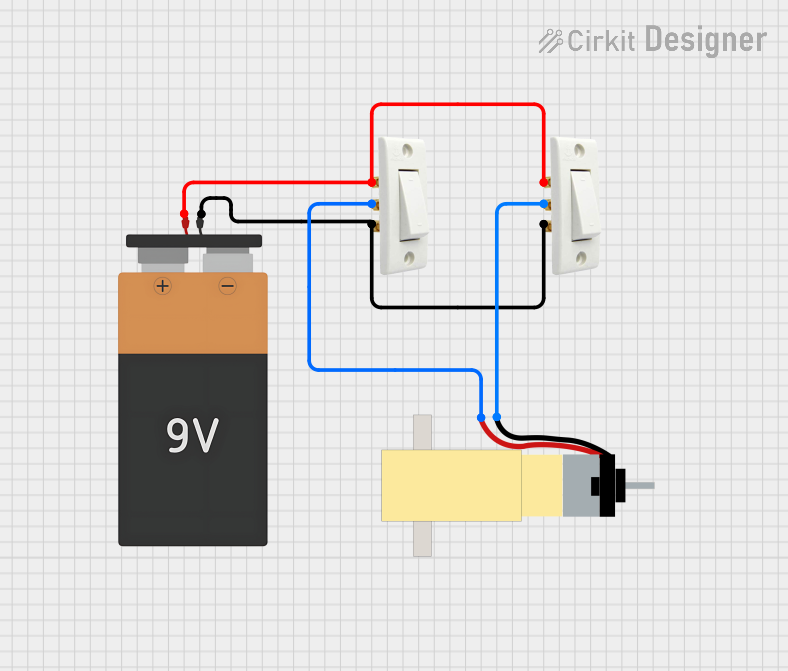
Explore Projects Built with 2 gang socket with wire
Common Applications and Use Cases
- Powering household appliances such as lamps, televisions, and chargers.
- Providing power to office equipment like computers and printers.
- Used in workshops to connect tools and machinery.
- Temporary power setups for events or construction sites.
Technical Specifications
Below are the key technical details for the 2 gang socket with wire:
| Parameter | Specification |
|---|---|
| Voltage Rating | 220-250V AC |
| Current Rating | 10A or 13A (depending on the model) |
| Number of Outlets | 2 |
| Wire Length | Typically 1.5m to 3m |
| Wire Type | 3-core cable (Live, Neutral, Earth) |
| Socket Type | Type G (UK), Type F (EU), or others |
| Material | Flame-retardant plastic housing |
| Mounting Type | Surface-mounted or flush-mounted |
| Safety Features | Childproof shutters, grounding pin |
Pin Configuration and Descriptions
The 2 gang socket with wire typically includes a 3-core cable with the following connections:
| Wire Color | Function | Description |
|---|---|---|
| Brown | Live (L) | Carries the current to the socket. |
| Blue | Neutral (N) | Returns the current to complete the circuit. |
| Green/Yellow | Earth (E) | Provides safety by grounding the socket. |
Usage Instructions
How to Use the Component in a Circuit
- Turn Off Power: Before installation, ensure the power supply to the circuit is turned off at the breaker.
- Prepare the Wires: Strip the insulation from the ends of the live, neutral, and earth wires.
- Connect the Wires:
- Connect the brown (live) wire to the terminal marked "L."
- Connect the blue (neutral) wire to the terminal marked "N."
- Connect the green/yellow (earth) wire to the terminal marked "E" or the grounding terminal.
- Secure the Socket: Mount the socket to the wall or surface using screws.
- Test the Connection: Turn the power back on and use a socket tester to verify proper wiring.
Important Considerations and Best Practices
- Always ensure the power is off before working with electrical components.
- Use a multimeter to confirm there is no voltage present before handling wires.
- Ensure the wire gauge is appropriate for the current rating of the socket.
- Avoid overloading the socket by connecting devices that exceed the total current rating.
- If unsure about installation, consult a licensed electrician.
Arduino UNO Integration
While a 2 gang socket with wire is not directly connected to an Arduino UNO, it can be used in projects involving relays to control AC devices. Below is an example of Arduino code to control a relay module connected to a 2 gang socket:
// Example: Controlling a relay to switch a 2 gang socket on/off
// Pin 7 is connected to the relay module's control pin

const int relayPin = 7; // Define the relay control pin

void setup() {
  pinMode(relayPin, OUTPUT); // Set the relay pin as an output
  digitalWrite(relayPin, LOW); // Ensure the relay is off initially
}

void loop() {
  digitalWrite(relayPin, HIGH); // Turn the relay (and socket) ON
  delay(5000); // Keep it ON for 5 seconds
  digitalWrite(relayPin, LOW); // Turn the relay (and socket) OFF
  delay(5000); // Keep it OFF for 5 seconds
}
Note: Ensure proper isolation between the Arduino and the AC circuit using a relay module with optocoupler protection.
Troubleshooting and FAQs
Common Issues Users Might Face
Socket Not Powering Devices:
- Cause: Loose or incorrect wiring.
- Solution: Double-check the wire connections to the live, neutral, and earth terminals.
Overheating Socket:
- Cause: Overloading the socket with high-power devices.
- Solution: Ensure the total current draw does not exceed the socket's rating.
Tripped Circuit Breaker:
- Cause: Short circuit or faulty wiring.
- Solution: Inspect the wiring for damage or incorrect connections.
Relay Not Controlling the Socket (if used with Arduino):
- Cause: Incorrect relay wiring or insufficient power to the relay module.
- Solution: Verify the relay module connections and ensure the Arduino provides sufficient current.
Solutions and Tips for Troubleshooting
- Use a socket tester to quickly diagnose wiring issues.
- Inspect the wire insulation for damage or wear.
- If the socket is not functioning after installation, test the voltage at the terminals using a multimeter.
- For Arduino-based projects, ensure the relay module is compatible with the socket's voltage and current ratings.
By following this documentation, users can safely and effectively install and use a 2 gang socket with wire in various applications.