How to Use RELAY MODULE: Examples, Pinouts, and Specs
Introduction
The MAYUR RELAY MODULE (Part ID: RELAY MODULE) is an electronic component designed to enable low-power signals to control high-power circuits. It is equipped with one or more relays, which function as electrically operated switches. This module is widely used in applications where electrical isolation and high-power control are required.
Explore Projects Built with RELAY MODULE


Explore Projects Built with RELAY MODULE
Common Applications and Use Cases
- Home automation systems for controlling lights, fans, and appliances.
- Industrial automation for motor control and process management.
- Robotics for switching high-power actuators or motors.
- IoT projects for remote device control.
- Automotive systems for controlling high-current devices like horns or lights.
Technical Specifications
The following table outlines the key technical details of the MAYUR RELAY MODULE:
| Parameter | Specification |
|---|---|
| Operating Voltage | 5V DC |
| Trigger Voltage | 3.3V to 5V DC |
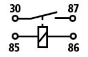
| Relay Type | SPDT (Single Pole Double Throw) |
| Maximum Load Voltage | 250V AC / 30V DC |
| Maximum Load Current | 10A |
| Isolation | Optocoupler-based electrical isolation |
| Dimensions | 50mm x 25mm x 18mm |
| Operating Temperature | -40°C to 85°C |
Pin Configuration and Descriptions
The MAYUR RELAY MODULE typically has the following pin configuration:
| Pin Name | Description |
|---|---|
| VCC | Power supply input (5V DC). |
| GND | Ground connection. |
| IN | Control signal input (3.3V to 5V logic level). |
| NO | Normally Open terminal of the relay. Connected to COM when the relay is active. |
| NC | Normally Closed terminal of the relay. Connected to COM when the relay is inactive. |
| COM | Common terminal of the relay. |
Usage Instructions
How to Use the Component in a Circuit
- Power the Module: Connect the VCC pin to a 5V DC power source and the GND pin to the ground.
- Control Signal: Connect the IN pin to a microcontroller (e.g., Arduino UNO) or any other control circuit capable of providing a 3.3V to 5V logic signal.
- Load Connection:
- Connect the device you want to control (e.g., a light bulb or motor) to the NO or NC terminal, depending on the desired behavior.
- Connect the other terminal of the device to the power source.
- The COM terminal should be connected to the power source or ground, depending on the circuit design.
- Trigger the Relay: When a HIGH signal (3.3V to 5V) is applied to the IN pin, the relay activates, connecting the NO terminal to COM. When the signal is LOW, the relay deactivates, connecting the NC terminal to COM.
Important Considerations and Best Practices
- Electrical Isolation: Ensure proper isolation between the low-power control circuit and the high-power load to prevent damage.
- Flyback Diode: If controlling an inductive load (e.g., a motor), use a flyback diode across the load to protect the relay from voltage spikes.
- Power Ratings: Do not exceed the maximum voltage and current ratings of the relay.
- Mounting: Secure the module in a well-ventilated area to prevent overheating.
Example: Connecting to an Arduino UNO
Below is an example of how to use the MAYUR RELAY MODULE with an Arduino UNO to control a light bulb:
Circuit Connections
- Connect the VCC pin of the relay module to the 5V pin of the Arduino.
- Connect the GND pin of the relay module to the GND pin of the Arduino.
- Connect the IN pin of the relay module to digital pin 7 of the Arduino.
- Connect the light bulb to the NO terminal and the power source to the COM terminal.
Arduino Code
// Define the relay control pin
const int relayPin = 7;

void setup() {
  // Set the relay pin as an output
  pinMode(relayPin, OUTPUT);
  // Start with the relay off
  digitalWrite(relayPin, LOW);
}

void loop() {
  // Turn the relay on (light bulb ON)
  digitalWrite(relayPin, HIGH);
  delay(5000); // Keep the light ON for 5 seconds

  // Turn the relay off (light bulb OFF)
  digitalWrite(relayPin, LOW);
  delay(5000); // Keep the light OFF for 5 seconds
}
Troubleshooting and FAQs
Common Issues and Solutions
Relay Not Activating:
- Cause: Insufficient control signal voltage.
- Solution: Ensure the IN pin receives a voltage between 3.3V and 5V.
Load Not Switching:
- Cause: Incorrect wiring of the load to the relay terminals.
- Solution: Verify the connections to the NO, NC, and COM terminals.
Overheating:
- Cause: Exceeding the relay's current or voltage ratings.
- Solution: Ensure the load does not exceed 10A or 250V AC / 30V DC.
Noise or Chattering:
- Cause: Unstable control signal or insufficient power supply.
- Solution: Use a stable power source and ensure proper grounding.
FAQs
Q1: Can I use the relay module with a 3.3V microcontroller?
A1: Yes, the relay module is compatible with 3.3V logic levels, but ensure the power supply to the module is 5V.
Q2: Can the relay module control DC motors?
A2: Yes, the relay module can control DC motors, but use a flyback diode to protect the relay from voltage spikes.
Q3: Is the relay module safe for high-power applications?
A3: Yes, as long as the load does not exceed the specified voltage and current ratings (250V AC / 30V DC, 10A).
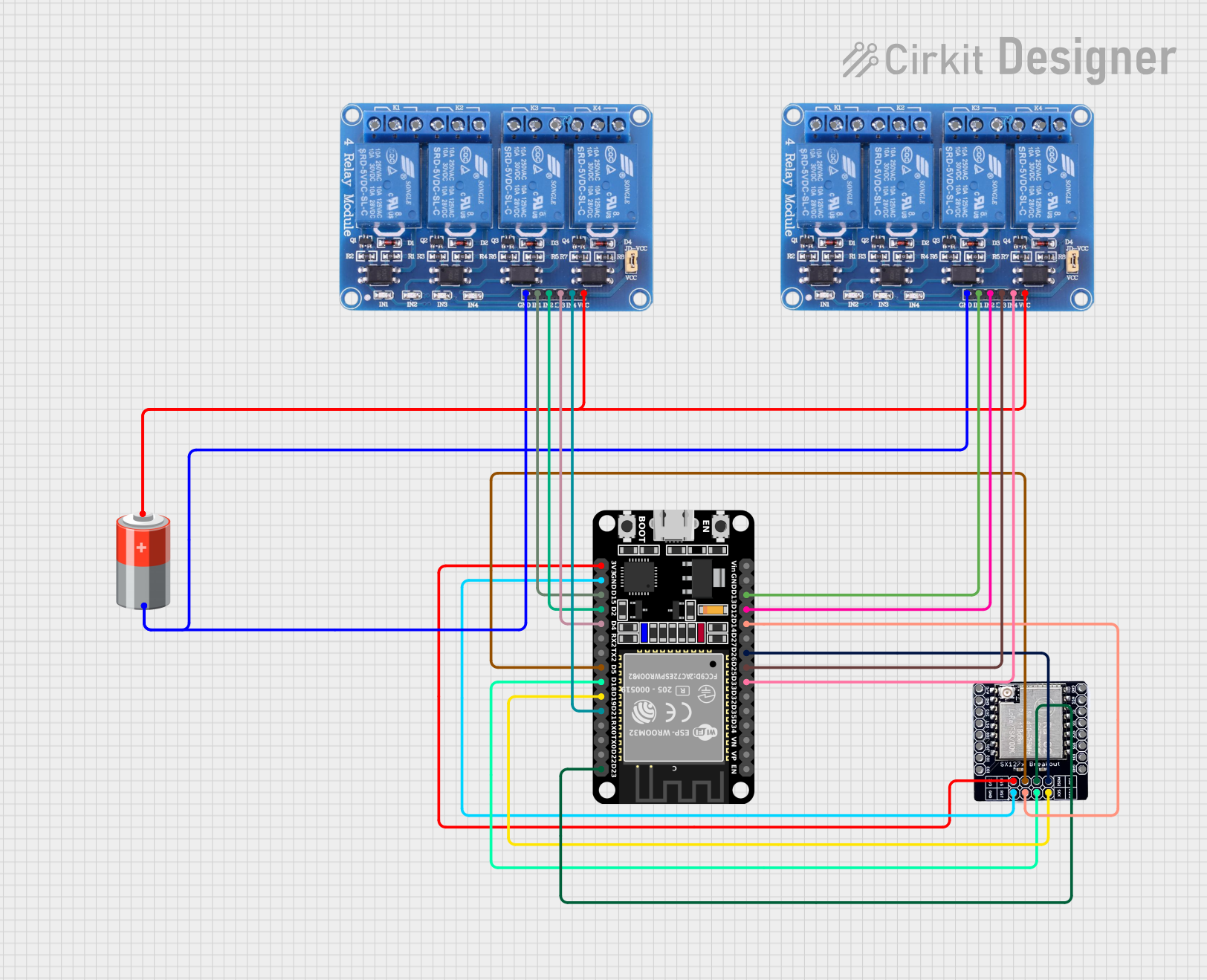
Q4: Can I use multiple relay modules with one microcontroller?
A4: Yes, you can use multiple modules, but ensure the microcontroller has enough GPIO pins and power capacity.