How to Use 12V/24V ออโต้ 20A MPPT: Examples, Pinouts, and Specs
Introduction
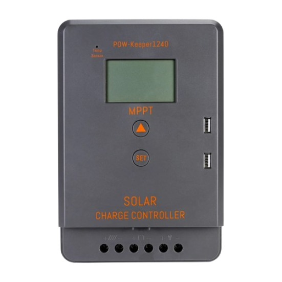
The 12V/24V ออโต้ 20A MPPT is a high-efficiency Maximum Power Point Tracking (MPPT) charge controller designed for solar power systems. It automatically detects and adjusts to 12V or 24V battery systems, ensuring optimal power transfer from solar panels to the battery. With a current handling capacity of up to 20A, this MPPT controller maximizes energy harvesting, reduces power loss, and extends battery life.
Explore Projects Built with 12V/24V ออโต้ 20A MPPT
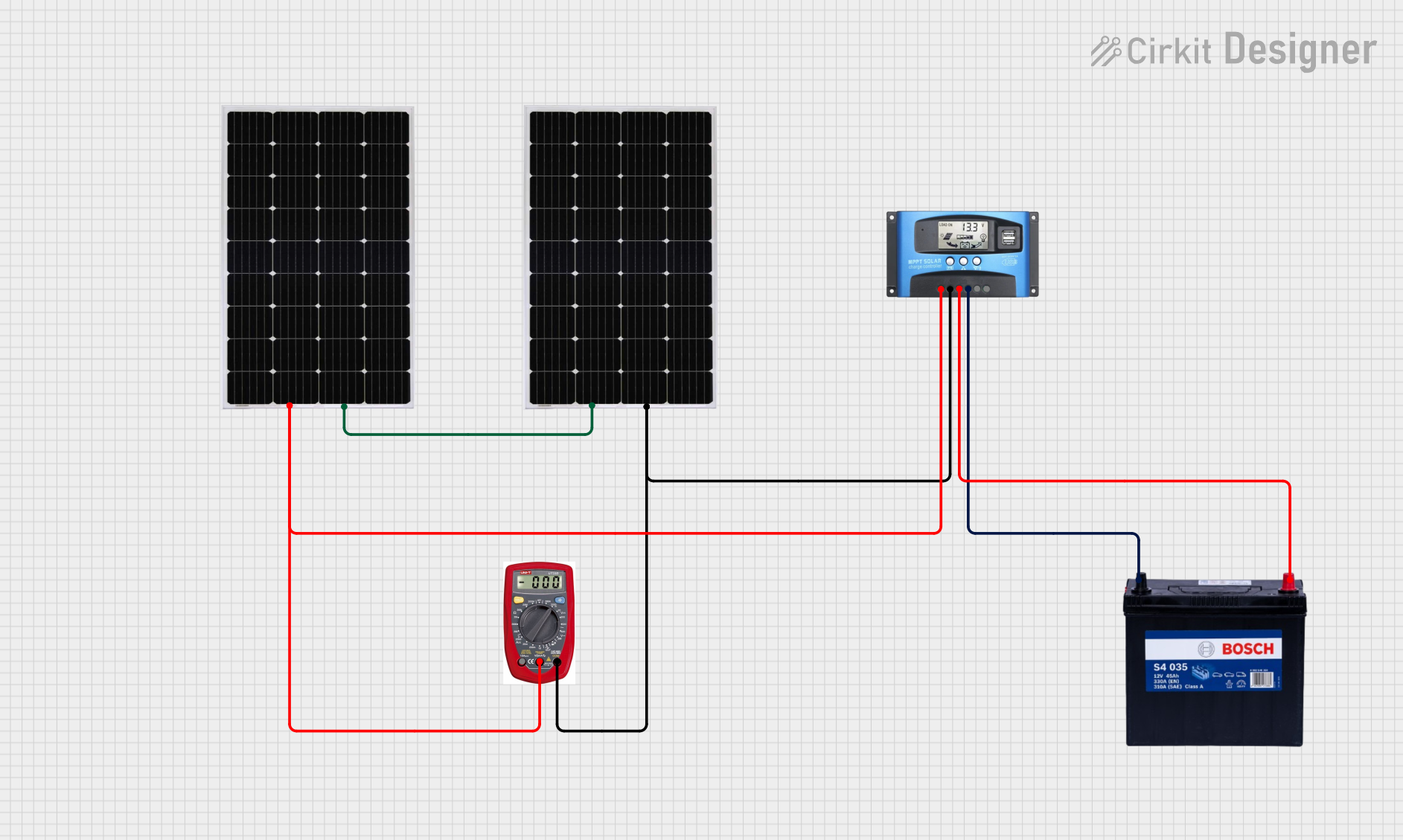
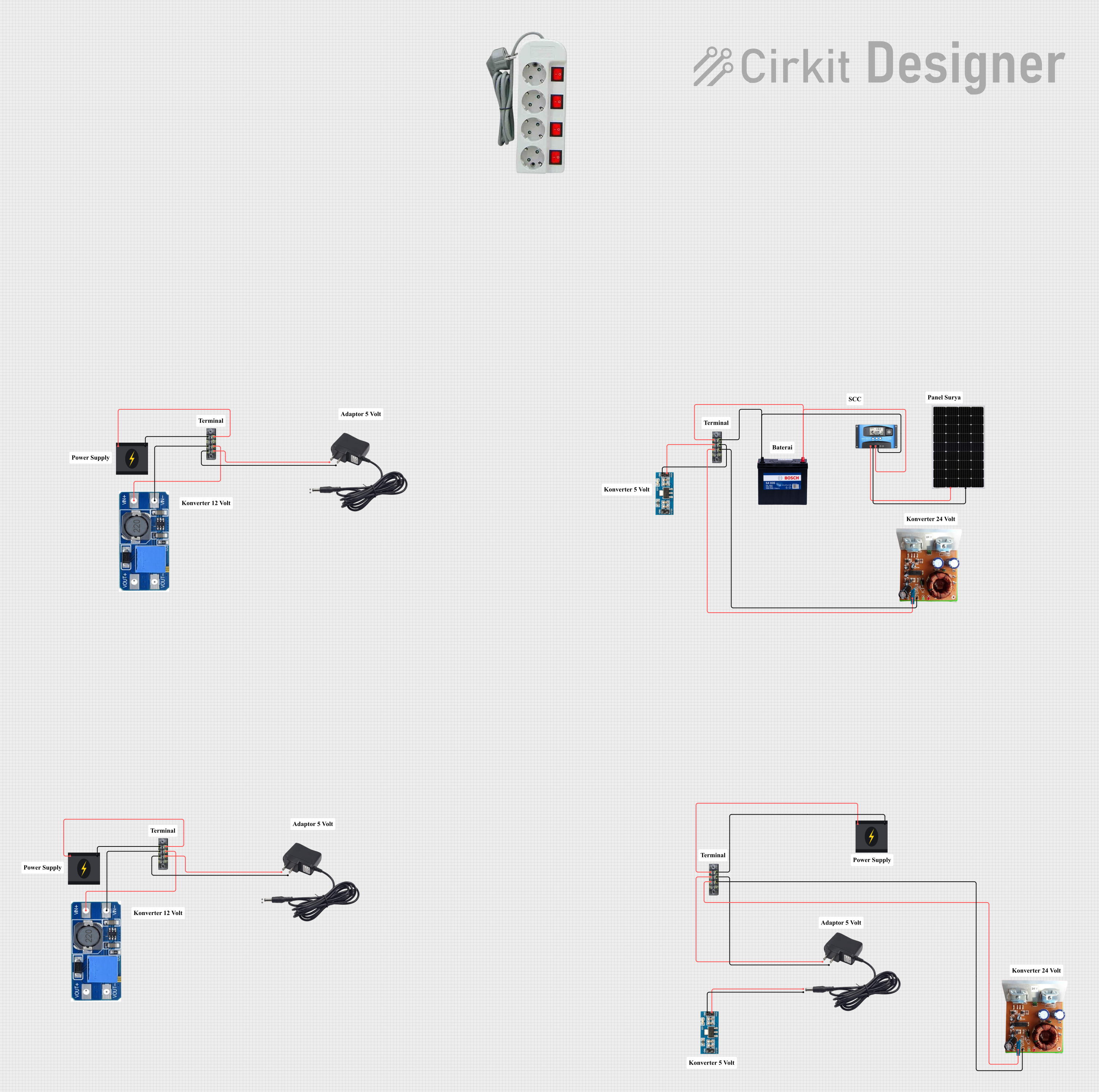
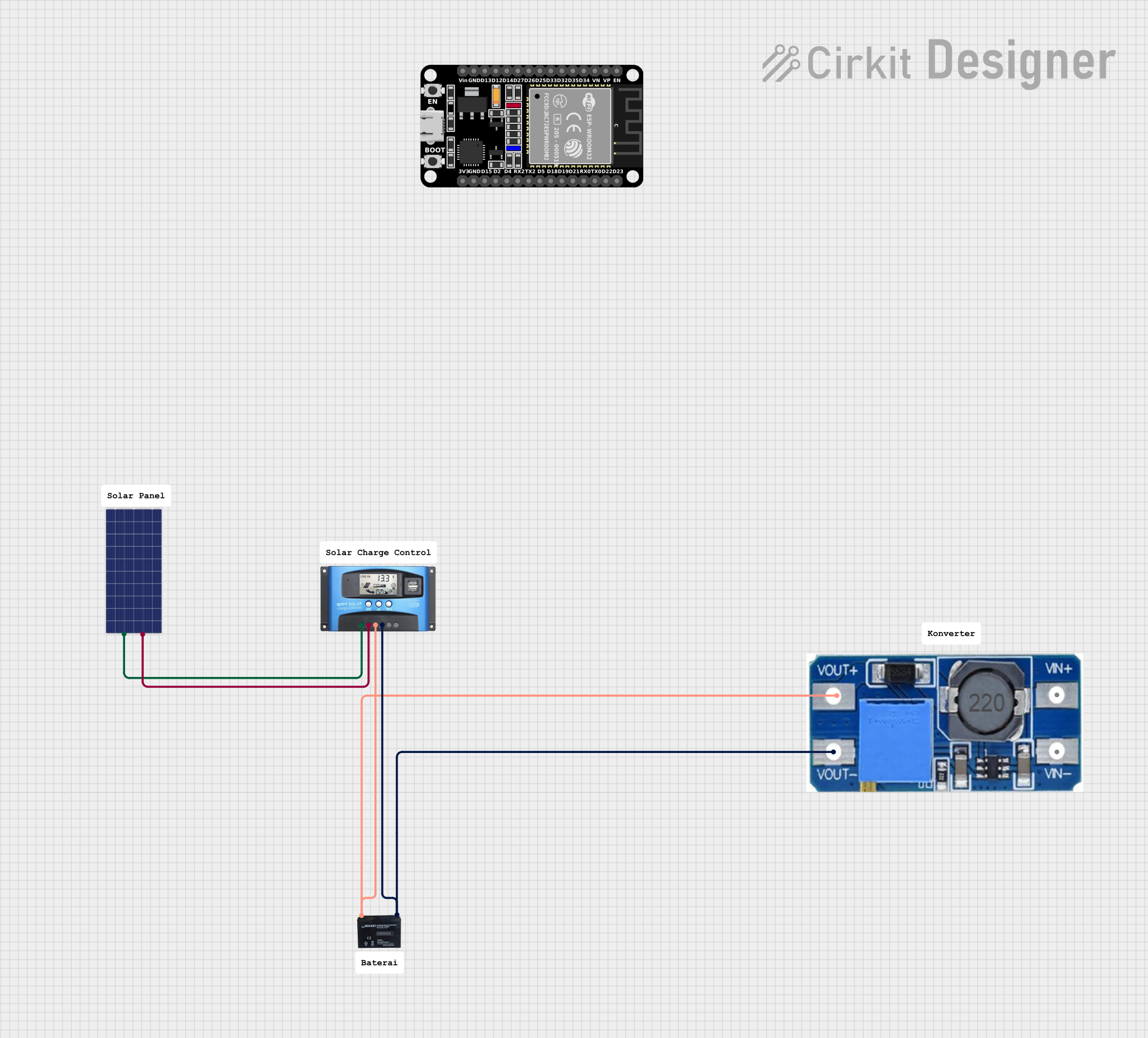
Explore Projects Built with 12V/24V ออโต้ 20A MPPT
Common Applications and Use Cases
- Solar-powered off-grid systems
- RVs, boats, and caravans
- Residential solar installations
- Industrial solar power systems
- Battery charging and maintenance for 12V/24V systems
Technical Specifications
Key Technical Details
- Input Voltage Range: 15V–100V DC
- Battery Voltage: Automatically detects 12V or 24V systems
- Maximum Current: 20A
- Efficiency: Up to 98%
- Operating Temperature: -20°C to 60°C
- Protection Features: Overcharge, over-discharge, short circuit, and reverse polarity protection
- Display: LCD for real-time monitoring of system parameters
- Communication Interface: RS485 (optional, for advanced monitoring)
Pin Configuration and Descriptions
The MPPT charge controller typically has the following terminals for connections:
| Pin/Terminal | Description |
|---|---|
| Solar Panel (+) | Positive terminal for connecting the solar panel input. |
| Solar Panel (-) | Negative terminal for connecting the solar panel input. |
| Battery (+) | Positive terminal for connecting the battery. |
| Battery (-) | Negative terminal for connecting the battery. |
| Load (+) | Positive terminal for connecting the DC load (optional). |
| Load (-) | Negative terminal for connecting the DC load (optional). |
| RS485 (optional) | Communication port for advanced monitoring and control (if supported). |
Usage Instructions
How to Use the Component in a Circuit
Connect the Solar Panel:
- Attach the positive and negative terminals of the solar panel to the corresponding "Solar Panel (+)" and "Solar Panel (-)" inputs on the MPPT controller.
- Ensure the solar panel's voltage is within the input range (15V–100V DC).
Connect the Battery:
- Connect the positive and negative terminals of the battery to the "Battery (+)" and "Battery (-)" terminals.
- The MPPT controller will automatically detect whether the battery is 12V or 24V.
Optional Load Connection:
- If you wish to power a DC load directly, connect the load's positive and negative terminals to the "Load (+)" and "Load (-)" terminals.
Power On:
- Once all connections are secure, the MPPT controller will power on and begin operation.
- Use the LCD display to monitor system parameters such as input voltage, output current, and battery status.
Important Considerations and Best Practices
- Ensure Proper Polarity: Always double-check the polarity of all connections to avoid damage to the controller or connected devices.
- Use Appropriate Wire Gauges: Select wires that can handle the maximum current (20A) to prevent overheating or voltage drops.
- Install in a Ventilated Area: Place the MPPT controller in a location with adequate airflow to prevent overheating.
- Fuse Protection: Install fuses on both the solar panel and battery connections for added safety.
- Monitor Regularly: Periodically check the LCD display or use the RS485 interface (if available) to monitor system performance.
Arduino UNO Integration Example
If you want to monitor the MPPT controller's output using an Arduino UNO via the RS485 interface, you can use the following example code:
#include <SoftwareSerial.h>

// Define RS485 communication pins
#define RX_PIN 10  // Arduino pin connected to RS485 module's RO (Receive Out)
#define TX_PIN 11  // Arduino pin connected to RS485 module's DI (Data In)
#define DE_PIN 9   // Arduino pin connected to RS485 module's DE (Driver Enable)
#define RE_PIN 8   // Arduino pin connected to RS485 module's RE (Receiver Enable)

SoftwareSerial rs485(RX_PIN, TX_PIN); // Initialize software serial for RS485

void setup() {
  pinMode(DE_PIN, OUTPUT); // Set DE pin as output
  pinMode(RE_PIN, OUTPUT); // Set RE pin as output

  digitalWrite(DE_PIN, LOW); // Set DE to low (receive mode)
  digitalWrite(RE_PIN, LOW); // Set RE to low (receive mode)

  rs485.begin(9600); // Start RS485 communication at 9600 baud rate
  Serial.begin(9600); // Start serial monitor for debugging

  Serial.println("MPPT RS485 Communication Initialized");
}

void loop() {
  // Request data from MPPT controller
  digitalWrite(DE_PIN, HIGH); // Enable transmit mode
  digitalWrite(RE_PIN, HIGH);
  rs485.write("Request Data"); // Replace with actual request command for your MPPT
  delay(10); // Wait for data to be sent
  digitalWrite(DE_PIN, LOW); // Enable receive mode
  digitalWrite(RE_PIN, LOW);

  // Read response from MPPT controller
  if (rs485.available()) {
    String response = "";
    while (rs485.available()) {
      response += (char)rs485.read();
    }
    Serial.println("MPPT Response: " + response);
  }

  delay(1000); // Wait 1 second before next request
}
Notes:
- Replace
"Request Data"with the actual command required by your MPPT controller's RS485 protocol. - Ensure you have an RS485-to-TTL module to interface the Arduino with the MPPT controller.
Troubleshooting and FAQs
Common Issues and Solutions
No Power or Display on the MPPT Controller:
- Cause: Incorrect wiring or insufficient solar panel voltage.
- Solution: Verify all connections and ensure the solar panel voltage is within the input range (15V–100V DC).
Battery Not Charging:
- Cause: Faulty battery connection or incorrect battery type.
- Solution: Check the battery connections and ensure the battery is a 12V or 24V system.
Overheating:
- Cause: Poor ventilation or excessive current draw.
- Solution: Install the MPPT controller in a well-ventilated area and ensure the load does not exceed 20A.
RS485 Communication Not Working:
- Cause: Incorrect wiring or baud rate mismatch.
- Solution: Verify the RS485 module connections and ensure the baud rate matches the MPPT controller's settings.
FAQs
Q: Can I use this MPPT controller with a 48V battery system?
A: No, this controller is designed for 12V and 24V systems only.Q: What happens if I connect the solar panel in reverse polarity?
A: The controller has reverse polarity protection, but it is always recommended to double-check connections to avoid potential damage.Q: Can I use this MPPT controller indoors?
A: Yes, but ensure it is installed in a dry, well-ventilated area to prevent overheating.Q: How do I reset the MPPT controller?
A: Disconnect all inputs (solar panel, battery, and load), wait for 30 seconds, and reconnect them in the correct order.
This documentation provides a comprehensive guide to using the 12V/24V ออโต้ 20A MPPT charge controller effectively and safely.