
How to Use Limit Switch: Examples, Pinouts, and Specs
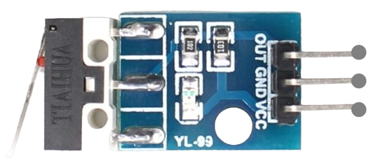
 Design with Limit Switch in Cirkit Designer
Introduction
A limit switch is an electromechanical device designed to detect the presence or absence of an object or the position of a moving part. It is commonly used in industrial and automation applications to control machinery or equipment. The switch operates by making or breaking an electrical connection when a physical actuator is triggered by an object.
Explore Projects Built with Limit Switch
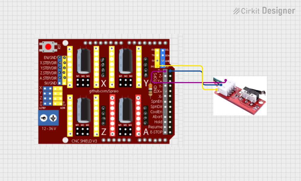 Open Project in Cirkit Designer
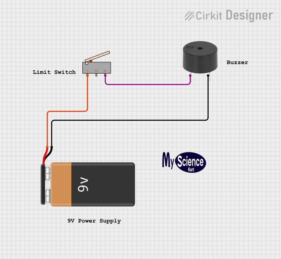 Open Project in Cirkit Designer
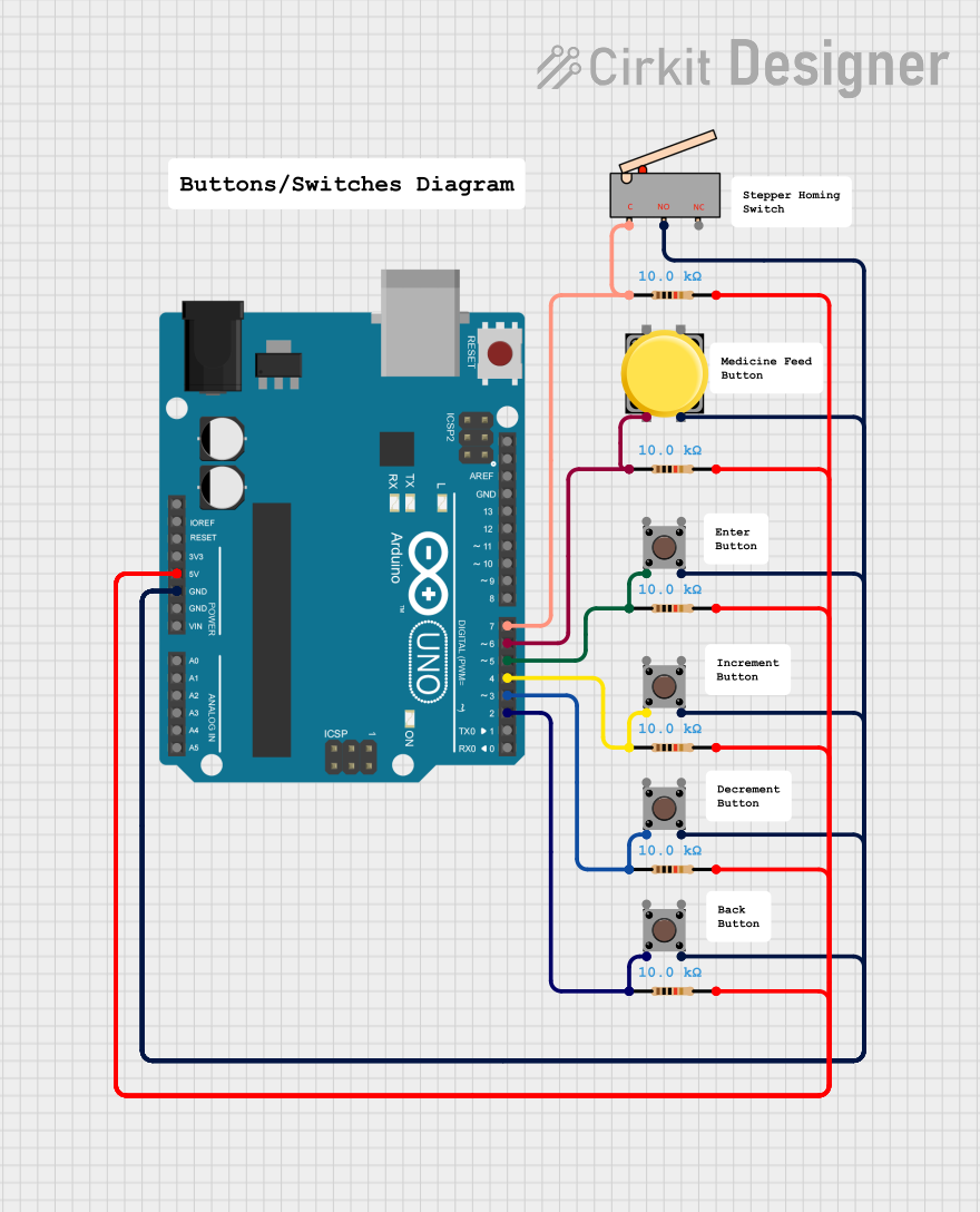 Open Project in Cirkit Designer
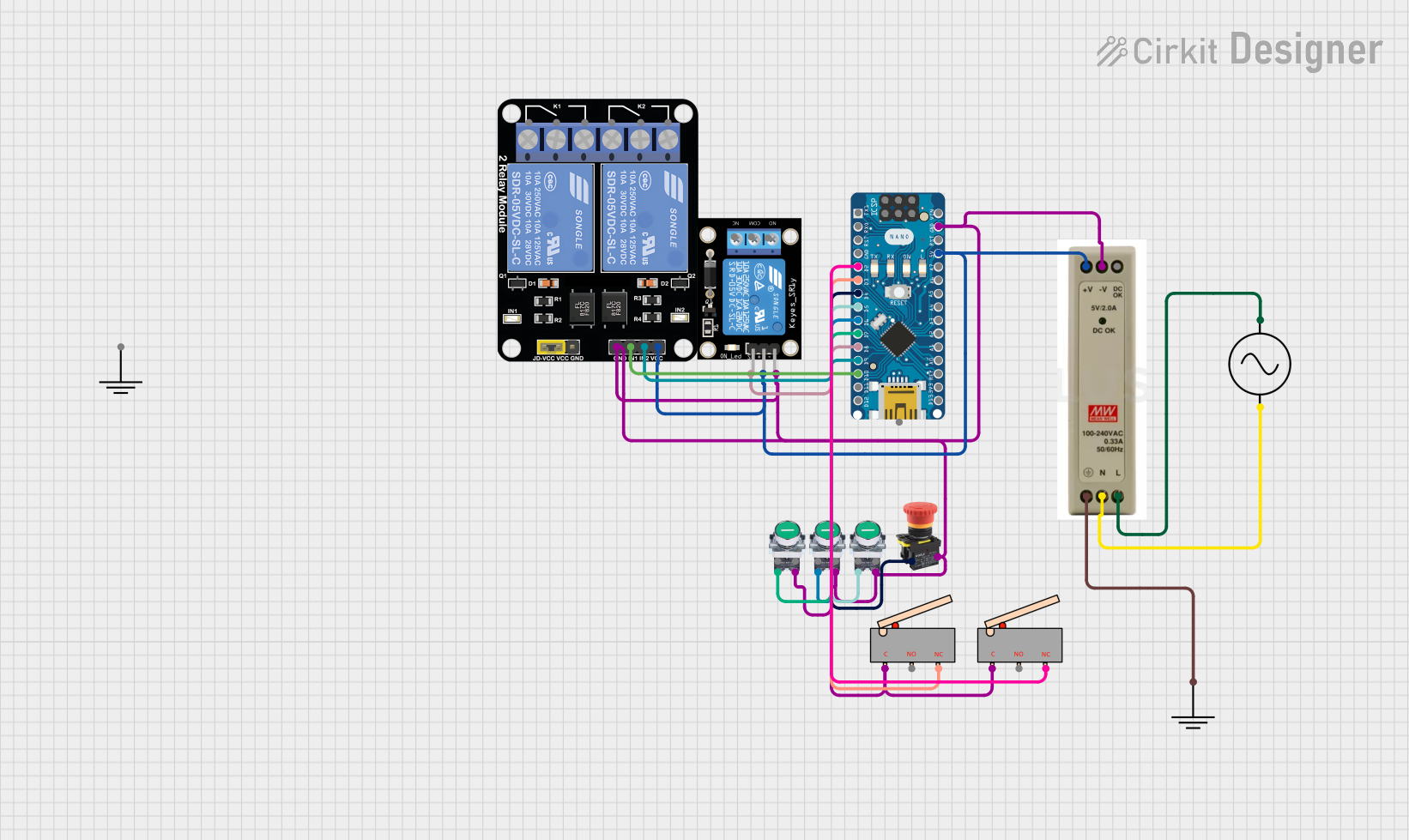 Open Project in Cirkit Designer
Explore Projects Built with Limit Switch
Open Project in Cirkit DesignerOpen Project in Cirkit DesignerOpen Project in Cirkit DesignerOpen Project in Cirkit DesignerCommon Applications and Use Cases
- Detecting the end of travel in linear or rotary motion systems
- Safety interlocks in machinery to prevent overtravel or damage
- Position sensing in conveyor belts, elevators, and robotic arms
- Automated systems requiring precise position feedback
Technical Specifications
Below are the key technical details for the Arduino UNO-compatible limit switch:
General Specifications
| Parameter | Value |
|---|---|
| Manufacturer | Arduino |
| Part ID | UNO |
| Operating Voltage | 5V DC |
| Maximum Current Rating | 5A |
| Contact Type | Normally Open (NO) / Normally Closed (NC) |
| Actuator Type | Lever, Roller, or Plunger |
| Mechanical Durability | 10 million operations |
| Electrical Durability | 500,000 operations |
| Operating Temperature | -25°C to 85°C |
Pin Configuration and Descriptions
| Pin Name | Description |
|---|---|
| COM | Common terminal for the switch |
| NO | Normally Open terminal (closed when actuated) |
| NC | Normally Closed terminal (open when actuated) |
Usage Instructions
How to Use the Limit Switch in a Circuit
Wiring the Limit Switch:
- Connect the
COMpin to the ground (GND) of your circuit. - Use the
NOpin if you want the circuit to close when the switch is actuated. - Use the
NCpin if you want the circuit to open when the switch is actuated. - For Arduino UNO, connect the
NOorNCpin to a digital input pin (e.g., D2) and use a pull-up or pull-down resistor as needed.
- Connect the
Example Circuit:
- Connect the
COMpin to GND. - Connect the
NOpin to Arduino digital pin D2. - Use a 10kΩ pull-up resistor between D2 and 5V to ensure a stable signal.
- Connect the
Arduino UNO Code Example: Below is an example code snippet to read the state of the limit switch:
// Define the pin connected to the limit switch
const int limitSwitchPin = 2;

void setup() {
  pinMode(limitSwitchPin, INPUT_PULLUP); // Set pin as input with internal pull-up
  Serial.begin(9600); // Initialize serial communication
}

void loop() {
  int switchState = digitalRead(limitSwitchPin); // Read the switch state

  if (switchState == LOW) {
    // Switch is pressed (NO is connected to COM)
    Serial.println("Limit switch activated!");
  } else {
    // Switch is not pressed
    Serial.println("Limit switch not activated.");
  }

  delay(500); // Delay for stability
}
Important Considerations and Best Practices
- Debouncing: Mechanical switches may produce noise or false signals when actuated. Use software debouncing or a capacitor to filter out noise.
- Voltage Compatibility: Ensure the operating voltage of the limit switch matches your circuit (e.g., 5V for Arduino UNO).
- Mounting: Securely mount the switch to prevent misalignment or damage during operation.
- Actuator Type: Choose the appropriate actuator (lever, roller, or plunger) based on your application.
Troubleshooting and FAQs
Common Issues and Solutions
Switch Not Responding:
- Cause: Incorrect wiring or loose connections.
- Solution: Verify the wiring and ensure all connections are secure.
False Triggering:
- Cause: Electrical noise or lack of debouncing.
- Solution: Implement software debouncing or add a capacitor across the switch terminals.
Arduino Not Detecting the Switch:
- Cause: Incorrect pin configuration or missing pull-up resistor.
- Solution: Ensure the pin is configured as
INPUT_PULLUPin the code or use an external pull-up resistor.
Switch Fails to Actuate:
- Cause: Misaligned actuator or physical obstruction.
- Solution: Check the actuator alignment and remove any obstructions.
FAQs
Q: Can I use the limit switch with a 3.3V microcontroller?
A: Yes, but ensure the switch operates reliably at 3.3V and adjust the pull-up resistor value accordingly.
Q: How do I debounce the limit switch in software?
A: Use a delay or a state-checking algorithm in your code to filter out rapid changes in the switch state.
Q: Can I use the limit switch for high-current applications?
A: The switch can handle up to 5A, but for higher currents, use it to control a relay or transistor.
Q: What is the difference between NO and NC terminals?
A: The NO terminal is open by default and closes when actuated, while the NC terminal is closed by default and opens when actuated. Choose based on your circuit requirements.