How to Use Controller 80x130: Examples, Pinouts, and Specs
Introduction
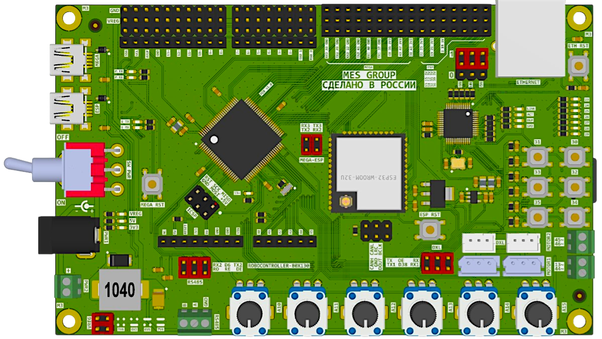
The Controller 80x130 is a versatile programmable device designed to manage and control the operation of electronic circuits. It features an integrated microcontroller capable of processing input signals and executing control algorithms efficiently. This component is ideal for applications requiring precise control, automation, and signal processing.
Explore Projects Built with Controller 80x130


Explore Projects Built with Controller 80x130
Common Applications and Use Cases
- Industrial automation systems
- Robotics and motor control
- Home automation and IoT devices
- Signal processing and data acquisition
- Embedded systems requiring real-time control
Technical Specifications
Key Technical Details
| Parameter | Value |
|---|---|
| Operating Voltage | 3.3V to 5V |
| Maximum Current | 500mA |
| Processor Type | 32-bit ARM Cortex-M4 |
| Clock Speed | 80 MHz |
| Flash Memory | 130 KB |
| RAM | 32 KB |
| Communication Protocols | UART, SPI, I2C, PWM |
| GPIO Pins | 20 |
| Operating Temperature | -40°C to 85°C |
| Dimensions | 40mm x 20mm x 5mm |
Pin Configuration and Descriptions
| Pin Number | Pin Name | Description |
|---|---|---|
| 1 | VCC | Power supply input (3.3V to 5V) |
| 2 | GND | Ground connection |
| 3 | GPIO1 | General-purpose input/output pin |
| 4 | GPIO2 | General-purpose input/output pin |
| 5 | GPIO3 | General-purpose input/output pin |
| 6 | GPIO4 | General-purpose input/output pin |
| 7 | UART_TX | UART transmit pin |
| 8 | UART_RX | UART receive pin |
| 9 | SPI_MOSI | SPI Master Out Slave In |
| 10 | SPI_MISO | SPI Master In Slave Out |
| 11 | SPI_SCK | SPI Clock |
| 12 | I2C_SDA | I2C Data Line |
| 13 | I2C_SCL | I2C Clock Line |
| 14 | PWM1 | Pulse Width Modulation output |
| 15 | PWM2 | Pulse Width Modulation output |
| 16 | ADC1 | Analog-to-Digital Converter input |
| 17 | ADC2 | Analog-to-Digital Converter input |
| 18 | RESET | Reset pin |
| 19 | INT | Interrupt pin |
| 20 | NC | Not connected |
Usage Instructions
How to Use the Component in a Circuit
- Power Supply: Connect the VCC pin to a 3.3V or 5V power source and the GND pin to the ground.
- Input/Output Connections: Use the GPIO pins for digital input/output operations. Configure them as needed in your code.
- Communication: Utilize UART, SPI, or I2C pins for communication with other devices or microcontrollers.
- PWM and ADC: Use the PWM pins for motor control or LED dimming, and the ADC pins for reading analog signals.
- Reset and Interrupt: Connect the RESET pin to a push button for manual resets and the INT pin for external interrupt signals.
Important Considerations and Best Practices
- Ensure the operating voltage does not exceed 5V to prevent damage to the component.
- Use appropriate pull-up or pull-down resistors for GPIO pins when necessary.
- Decouple the power supply with a 0.1µF capacitor close to the VCC pin to reduce noise.
- Avoid leaving unused pins floating; connect them to GND or VCC as required.
- For high-speed communication, ensure proper termination and shielding of communication lines.
Example Code for Arduino UNO
The following example demonstrates how to interface the Controller 80x130 with an Arduino UNO using UART communication.
// Example: Communicating with Controller 80x130 via UART
// Ensure the TX pin of the Arduino is connected to the RX pin of the Controller
// and the RX pin of the Arduino is connected to the TX pin of the Controller.

void setup() {
  Serial.begin(9600); // Initialize UART communication at 9600 baud rate
  delay(1000);        // Wait for the Controller to initialize
  Serial.println("Controller 80x130 Ready"); // Send initialization message
}

void loop() {
  // Send a command to the Controller
  Serial.println("READ_SENSOR");

  // Wait for a response from the Controller
  if (Serial.available() > 0) {
    String response = Serial.readString(); // Read the response
    Serial.print("Controller Response: ");
    Serial.println(response); // Print the response to the Serial Monitor
  }

  delay(1000); // Wait 1 second before sending the next command
}
Troubleshooting and FAQs
Common Issues and Solutions
No Response from the Controller
- Cause: Incorrect UART connections or baud rate mismatch.
- Solution: Verify that the TX and RX pins are correctly connected and the baud rate matches the Controller's configuration.
Overheating
- Cause: Exceeding the maximum current or voltage ratings.
- Solution: Ensure the power supply voltage is within the 3.3V to 5V range and the current does not exceed 500mA.
Unstable Operation
- Cause: Noise in the power supply or floating pins.
- Solution: Add decoupling capacitors near the VCC pin and connect unused pins to GND or VCC.
PWM Output Not Working
- Cause: Incorrect pin configuration or missing load.
- Solution: Verify that the PWM pins are correctly configured in the code and connected to a valid load.
FAQs
Q: Can the Controller 80x130 operate at 12V?
A: No, the maximum operating voltage is 5V. Using 12V will damage the component.Q: How many devices can I connect via I2C?
A: The Controller 80x130 supports up to 127 devices on the I2C bus, depending on the address configuration.Q: Is the Controller compatible with 1.8V logic levels?
A: No, the GPIO pins are designed for 3.3V or 5V logic levels. Use a level shifter for 1.8V devices.Q: Can I program the Controller directly?
A: Yes, the Controller 80x130 can be programmed using standard development tools compatible with ARM Cortex-M4 processors.