How to Use CAM SWITCH: Examples, Pinouts, and Specs
Introduction
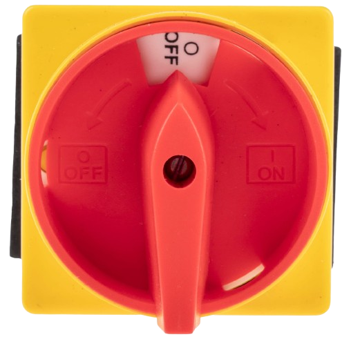
A cam switch is an electromechanical switch that uses a rotating cam mechanism to open or close electrical circuits. It is designed to provide precise control over multiple circuit configurations, making it ideal for applications requiring multiple positions or settings. Cam switches are widely used in industrial machinery, control panels, and electrical distribution systems. Their robust design and versatility make them suitable for both AC and DC circuits.
Explore Projects Built with CAM SWITCH
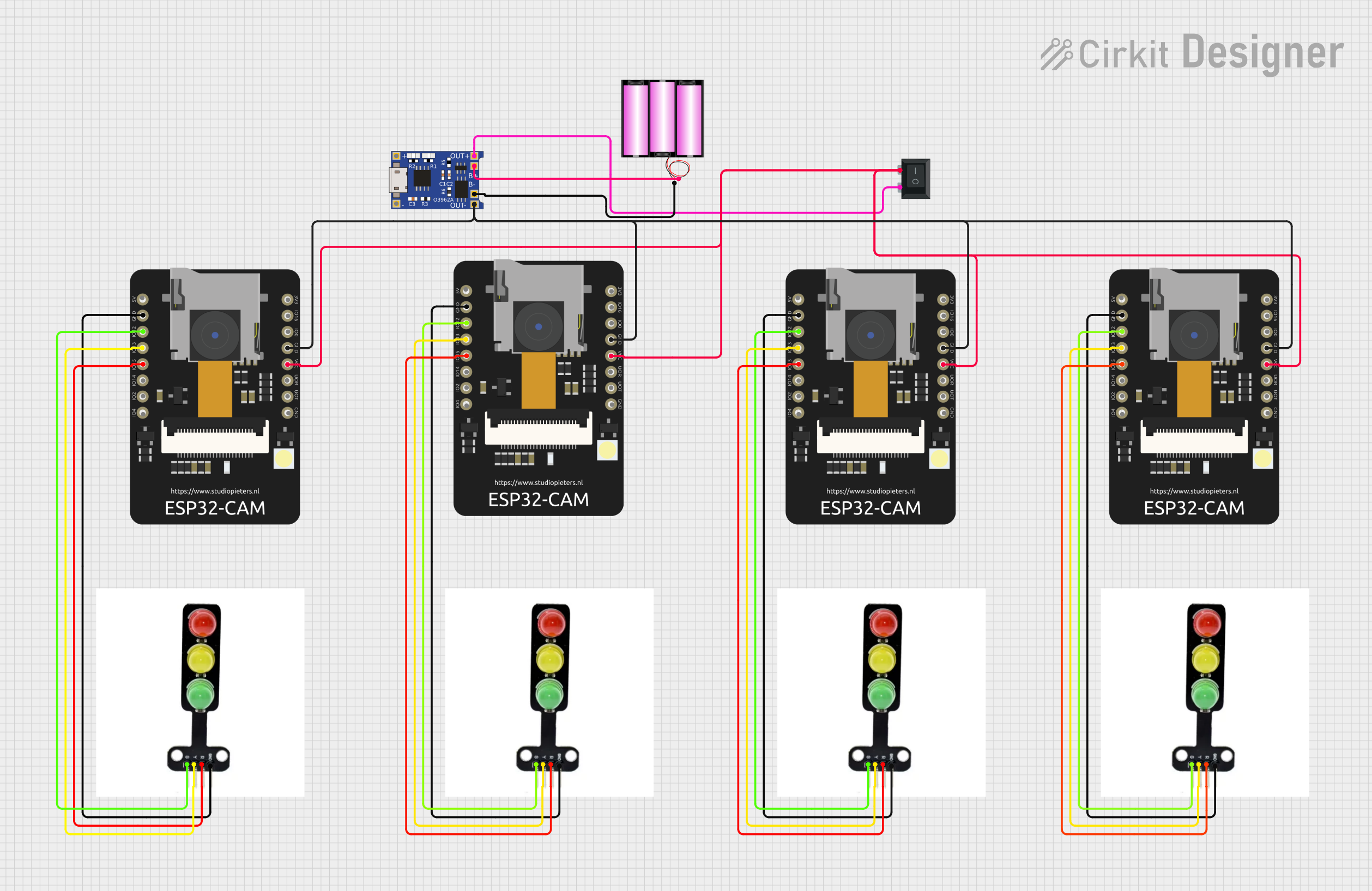


Explore Projects Built with CAM SWITCH
Common Applications
- Industrial machinery control
- Motor control and reversing
- Electrical distribution systems
- Selector switches in control panels
- Testing and measurement equipment
Technical Specifications
Key Technical Details
| Parameter | Specification |
|---|---|
| Rated Voltage | Up to 690V AC / 440V DC |
| Rated Current | 10A to 200A (varies by model) |
| Number of Positions | 2 to 12 positions |
| Switching Angle | 30°, 45°, 60°, or 90° (depending on model) |
| Contact Configuration | Single-pole, double-pole, or multi-pole |
| Insulation Resistance | ≥ 100 MΩ |
| Operating Temperature | -25°C to +55°C |
| Mechanical Life | ≥ 1,000,000 operations |
| Electrical Life | ≥ 100,000 operations |
Pin Configuration and Descriptions
The pin configuration of a cam switch depends on its specific model and application. Below is an example of a typical 3-pole, 4-position cam switch:
| Pin Number | Description |
|---|---|
| 1 | Input terminal for Pole 1 |
| 2 | Output terminal for Pole 1 (Position 1) |
| 3 | Output terminal for Pole 1 (Position 2) |
| 4 | Input terminal for Pole 2 |
| 5 | Output terminal for Pole 2 (Position 1) |
| 6 | Output terminal for Pole 2 (Position 2) |
| 7 | Input terminal for Pole 3 |
| 8 | Output terminal for Pole 3 (Position 1) |
| 9 | Output terminal for Pole 3 (Position 2) |
Note: The actual pin configuration may vary depending on the manufacturer and model. Always refer to the datasheet for your specific cam switch.
Usage Instructions
How to Use a Cam Switch in a Circuit
Determine the Application Requirements:
- Identify the number of poles, positions, and switching angles required for your application.
- Verify the voltage and current ratings of the cam switch match your circuit specifications.
Wiring the Cam Switch:
- Connect the input terminals to the power source or control circuit.
- Connect the output terminals to the load or device being controlled.
- Ensure proper insulation and secure connections to avoid short circuits.
Mounting the Cam Switch:
- Install the cam switch in a suitable enclosure or control panel.
- Use the mounting holes or brackets provided by the manufacturer.
Testing the Circuit:
- Rotate the cam switch to each position and verify the circuit operates as intended.
- Use a multimeter to check continuity and ensure proper switching.
Important Considerations and Best Practices
- Always disconnect power before wiring or servicing the cam switch.
- Use appropriately rated wires and terminals to handle the current and voltage.
- Avoid exceeding the rated electrical and mechanical life of the switch.
- For high-current applications, ensure proper heat dissipation and ventilation.
- Regularly inspect the switch for wear and tear, especially in industrial environments.
Example: Connecting a Cam Switch to an Arduino UNO
While cam switches are typically used in industrial applications, they can also be integrated into microcontroller projects for manual input. Below is an example of how to use a cam switch with an Arduino UNO to read its position:
// Example: Reading a 4-position cam switch with Arduino UNO
// Connect the cam switch outputs to Arduino digital pins 2, 3, 4, and 5.

const int camSwitchPins[] = {2, 3, 4, 5}; // Define cam switch pins
int switchState[4]; // Array to store the state of each position

void setup() {
  Serial.begin(9600); // Initialize serial communication
  for (int i = 0; i < 4; i++) {
    pinMode(camSwitchPins[i], INPUT_PULLUP); // Set pins as input with pull-up
  }
}

void loop() {
  for (int i = 0; i < 4; i++) {
    switchState[i] = digitalRead(camSwitchPins[i]); // Read each pin state
  }

  // Print the position of the cam switch
  Serial.print("Cam Switch Position: ");
  for (int i = 0; i < 4; i++) {
    Serial.print(switchState[i]);
    Serial.print(" ");
  }
  Serial.println();

  delay(500); // Delay for readability
}
Note: In this example, the cam switch outputs are connected to digital pins on the Arduino. The INPUT_PULLUP mode ensures the pins are not left floating when the switch is open.
Troubleshooting and FAQs
Common Issues
Switch Does Not Operate:
- Cause: Loose or incorrect wiring.
- Solution: Verify all connections and ensure the input terminals are properly connected to the power source.
Switch Fails to Change Positions:
- Cause: Mechanical wear or obstruction in the cam mechanism.
- Solution: Inspect the switch for physical damage and clean any debris.
Overheating or Burnt Contacts:
- Cause: Exceeding the rated current or voltage.
- Solution: Use a switch with appropriate ratings for your application.
Incorrect Circuit Operation:
- Cause: Miswiring or incorrect pin configuration.
- Solution: Double-check the wiring and refer to the datasheet for the correct pinout.
FAQs
Q: Can a cam switch be used for DC circuits?
A: Yes, cam switches can be used for both AC and DC circuits, provided the voltage and current ratings are within the specified limits.
Q: How do I select the right cam switch for my application?
A: Consider the number of poles, positions, switching angle, and electrical ratings required for your circuit. Refer to the manufacturer's catalog for available options.
Q: Can I repair a damaged cam switch?
A: Minor issues like loose connections can be fixed, but significant mechanical or electrical damage typically requires replacing the switch.
Q: Are cam switches waterproof?
A: Some cam switches are designed with IP-rated enclosures for water and dust resistance. Check the product specifications for details.