How to Use dspic30f4012: Examples, Pinouts, and Specs
Introduction
The dsPIC30F4012 is a 16-bit Digital Signal Controller (DSC) manufactured by Microchip Technology. It combines the performance of a Digital Signal Processor (DSP) with the simplicity of a microcontroller, making it ideal for high-performance embedded applications. With a processing speed of up to 30 MIPS (Million Instructions Per Second), integrated analog peripherals, and versatile communication interfaces, the dsPIC30F4012 is well-suited for applications such as motor control, digital signal processing, power conversion, and general-purpose embedded control.
Explore Projects Built with dspic30f4012


Explore Projects Built with dspic30f4012
Common Applications
- Motor control (e.g., BLDC, PMSM, and ACIM motors)
- Power inverters and converters
- Audio signal processing
- Industrial automation and control
- Embedded systems requiring real-time performance
Technical Specifications
Key Technical Details
| Parameter | Value |
|---|---|
| Core Architecture | 16-bit Digital Signal Controller (DSC) |
| Maximum Clock Speed | 30 MIPS |
| Program Memory (Flash) | 24 KB |
| Data Memory (RAM) | 2 KB |
| Operating Voltage Range | 2.5V to 5.5V |
| I/O Pins | 21 |
| Communication Interfaces | UART, SPI, I2C, CAN |
| Analog Peripherals | 2x 10-bit ADC modules (up to 12 inputs) |
| PWM Channels | 6 |
| Timers | 5 (16-bit) |
| Package Options | 28-pin SPDIP, SOIC, SSOP, QFN |
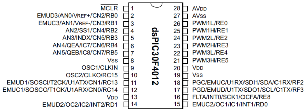
Pin Configuration and Descriptions
The dsPIC30F4012 is available in a 28-pin package. Below is the pin configuration and description:
| Pin No. | Pin Name | Type | Description |
|---|---|---|---|
| 1 | VDD | Power | Positive supply voltage |
| 2 | VSS | Power | Ground |
| 3 | OSC1/CLKI | Input | Oscillator input or external clock input |
| 4 | OSC2/CLKO | Output | Oscillator output or clock output |
| 5 | MCLR | Input | Master Clear (Reset) input |
| 6 | AN0 | Analog | Analog input channel 0 |
| 7 | AN1 | Analog | Analog input channel 1 |
| 8 | PGD | Digital I/O | Programming data line |
| 9 | PGC | Digital I/O | Programming clock line |
| 10 | RB0 | Digital I/O | General-purpose I/O or external interrupt |
| 11 | RB1 | Digital I/O | General-purpose I/O or external interrupt |
| 12 | RB2 | Digital I/O | General-purpose I/O or external interrupt |
| 13 | RB3 | Digital I/O | General-purpose I/O or external interrupt |
| 14 | VSS | Power | Ground |
| 15 | VDD | Power | Positive supply voltage |
| 16 | RC0 | Digital I/O | General-purpose I/O |
| 17 | RC1 | Digital I/O | General-purpose I/O |
| 18 | RC2 | Digital I/O | General-purpose I/O |
| 19 | RC3 | Digital I/O | General-purpose I/O |
| 20 | RC4 | Digital I/O | General-purpose I/O |
| 21 | RC5 | Digital I/O | General-purpose I/O |
| 22 | RC6 | Digital I/O | General-purpose I/O |
| 23 | RC7 | Digital I/O | General-purpose I/O |
| 24 | RD0 | Digital I/O | General-purpose I/O |
| 25 | RD1 | Digital I/O | General-purpose I/O |
| 26 | RD2 | Digital I/O | General-purpose I/O |
| 27 | RD3 | Digital I/O | General-purpose I/O |
| 28 | RD4 | Digital I/O | General-purpose I/O |
Usage Instructions
How to Use the dsPIC30F4012 in a Circuit
- Power Supply: Ensure the operating voltage is within the range of 2.5V to 5.5V. Connect VDD to the positive supply and VSS to ground.
- Clock Configuration: Use an external crystal oscillator or clock source connected to the OSC1 and OSC2 pins. Alternatively, configure the internal oscillator if available.
- Reset Pin: Connect the MCLR pin to a pull-up resistor (typically 10kΩ) to VDD for proper reset functionality.
- Programming: Use the PGD and PGC pins for in-circuit programming with a compatible programmer (e.g., Microchip's ICD3 or PICkit).
- Analog Inputs: Connect analog signals to the ANx pins for ADC functionality. Configure the ADC module in software.
- PWM Outputs: Use the PWM channels for motor control or other applications requiring pulse-width modulation.
- Communication Interfaces: Utilize UART, SPI, I2C, or CAN for communication with other devices.
Important Considerations and Best Practices
- Decoupling Capacitors: Place 0.1µF decoupling capacitors close to the VDD and VSS pins to reduce noise.
- Unused Pins: Configure unused pins as outputs or connect them to ground through pull-down resistors to avoid floating states.
- Programming Voltage: Ensure the programming voltage is within the specified range to avoid damaging the device.
- Thermal Management: If operating at high speeds or in demanding environments, ensure proper heat dissipation.
Example: Interfacing dsPIC30F4012 with Arduino UNO
The dsPIC30F4012 can communicate with an Arduino UNO via UART. Below is an example Arduino code to send data to the dsPIC30F4012:
// Arduino UNO UART Communication with dsPIC30F4012
// Sends a message to the dsPIC30F4012 via Serial

void setup() {
  Serial.begin(9600); // Initialize UART at 9600 baud rate
}

void loop() {
  Serial.println("Hello, dsPIC30F4012!"); // Send data to dsPIC
  delay(1000); // Wait for 1 second
}
On the dsPIC30F4012 side, configure the UART module in software to receive the data.
Troubleshooting and FAQs
Common Issues and Solutions
Device Not Responding
- Cause: Incorrect power supply or clock configuration.
- Solution: Verify the power supply voltage and ensure the oscillator is correctly configured.
Programming Failure
- Cause: Improper connection to the PGD and PGC pins or incompatible programmer.
- Solution: Check the connections and use a supported programmer (e.g., PICkit or ICD3).
Analog Inputs Not Working
- Cause: ADC module not initialized or incorrect pin configuration.
- Solution: Ensure the ADC module is properly configured in software and the analog pins are correctly connected.
Communication Issues
- Cause: Mismatched baud rates or incorrect wiring.
- Solution: Verify the baud rate settings and check the connections for UART, SPI, I2C, or CAN.
FAQs
Q: Can the dsPIC30F4012 operate without an external oscillator?
- A: Yes, it can use the internal oscillator, but an external oscillator is recommended for precise timing.
Q: What is the maximum ADC sampling rate?
- A: The maximum ADC sampling rate is approximately 500 ksps (kilo-samples per second).
Q: Can I use the dsPIC30F4012 for motor control?
- A: Yes, it is specifically designed for motor control applications with integrated PWM and ADC modules.
Q: How do I protect the MCLR pin?
- A: Use a pull-up resistor (10kΩ) and optionally a diode to VDD for additional protection.
This concludes the documentation for the dsPIC30F4012. For further details, refer to the official datasheet provided by Microchip Technology.