How to Use 24V_SMPS: Examples, Pinouts, and Specs
Introduction
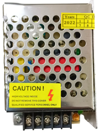
A 24V Switch Mode Power Supply (SMPS) is an electronic device designed to convert an input AC voltage (typically 110V or 220V) into a stable 24V DC output. It utilizes high-frequency switching technology to achieve efficient power conversion while minimizing heat generation. This makes it a reliable and compact solution for powering various electronic devices and systems.
Explore Projects Built with 24V_SMPS


Explore Projects Built with 24V_SMPS
Common Applications and Use Cases
- Industrial automation systems
- LED lighting systems
- CNC machines and 3D printers
- Robotics and motor controllers
- Telecommunications equipment
- Battery charging systems
Technical Specifications
Below are the key technical details and pin configurations for a typical 24V SMPS:
Key Technical Details
| Parameter | Value |
|---|---|
| Input Voltage Range | 100-240V AC, 50/60Hz |
| Output Voltage | 24V DC |
| Output Current | 2A to 10A (varies by model) |
| Power Output | 48W to 240W (varies by model) |
| Efficiency | ≥85% |
| Ripple and Noise | ≤120mVp-p |
| Operating Temperature | -10°C to +50°C |
| Protection Features | Overload, Overvoltage, Short Circuit |
Pin Configuration and Descriptions
| Pin Name | Description |
|---|---|
| L (Line) | AC live input (110V/220V AC) |
| N (Neutral) | AC neutral input |
| GND (Ground) | Earth/ground connection for safety |
| V+ | Positive 24V DC output |
| V- | Negative 24V DC output (ground) |
| Adjust (Trim) | Output voltage adjustment (optional) |
Usage Instructions
How to Use the Component in a Circuit
Input Connection:
- Connect the AC input terminals (
LandN) to the mains power supply (110V or 220V AC). - Ensure the ground (
GND) terminal is properly connected to the earth for safety.
- Connect the AC input terminals (
Output Connection:
- Connect the
V+terminal to the positive input of your load or circuit. - Connect the
V-terminal to the ground or negative input of your load.
- Connect the
Voltage Adjustment (if applicable):
- Some 24V SMPS units include a trim potentiometer to fine-tune the output voltage.
- Use a small screwdriver to adjust the trim potentiometer while monitoring the output voltage with a multimeter.
Load Considerations:
- Ensure the total load current does not exceed the rated output current of the SMPS.
- For inductive loads (e.g., motors), consider adding a flyback diode to protect the SMPS from voltage spikes.
Important Considerations and Best Practices
- Ventilation: Ensure adequate airflow around the SMPS to prevent overheating.
- Mounting: Secure the SMPS in a well-ventilated, dry location away from moisture and dust.
- Fusing: Use an appropriate fuse on the input side to protect against overcurrent conditions.
- Isolation: Avoid direct contact with the SMPS while it is powered to prevent electric shock.
Example: Connecting to an Arduino UNO
A 24V SMPS can be used to power an Arduino UNO via a step-down voltage regulator (e.g., LM2596) to convert 24V to 5V. Below is an example circuit and Arduino code:
Circuit Setup
- Connect the
V+andV-terminals of the SMPS to the input of the LM2596 regulator. - Adjust the LM2596 output to 5V using its potentiometer.
- Connect the 5V output of the LM2596 to the Arduino UNO's
5VandGNDpins.
Arduino Code Example
// Example code to blink an LED connected to pin 13 of the Arduino UNO
// Ensure the Arduino is powered via the 5V output of the LM2596 regulator

void setup() {
  pinMode(13, OUTPUT); // Set pin 13 as an output
}

void loop() {
  digitalWrite(13, HIGH); // Turn the LED on
  delay(1000);            // Wait for 1 second
  digitalWrite(13, LOW);  // Turn the LED off
  delay(1000);            // Wait for 1 second
}
Troubleshooting and FAQs
Common Issues and Solutions
| Issue | Possible Cause | Solution |
|---|---|---|
| No output voltage | Incorrect input connection | Verify L and N connections. |
| Blown fuse | Check and replace the input fuse. | |
| Output voltage too high/low | Misadjusted trim potentiometer | Adjust the trim potentiometer. |
| Overloaded SMPS | Reduce the load to within rated limits. | |
| SMPS overheating | Poor ventilation | Ensure proper airflow around the unit. |
| Overloaded or shorted output | Check the load and wiring. | |
| Noise or ripple in output voltage | Insufficient filtering | Add additional capacitors at the load. |
FAQs
Can I use a 24V SMPS to power a 12V device?
- Yes, but you will need a step-down voltage regulator to convert 24V to 12V.
What happens if I exceed the rated current?
- The SMPS will activate its overload protection, shutting down the output to prevent damage.
Is the SMPS safe to use with sensitive electronics?
- Yes, but ensure the ripple and noise specifications meet the requirements of your device. You can add additional filtering if needed.
Can I use the SMPS outdoors?
- Only if it is specifically rated for outdoor use (IP-rated). Otherwise, keep it in a dry, protected environment.
By following this documentation, you can safely and effectively use a 24V SMPS in your projects.