How to Use Little Soundie: Examples, Pinouts, and Specs
Introduction
The Little Soundie is a compact audio playback module designed for easy integration into DIY projects. It allows users to store and play back audio files, making it ideal for applications such as custom greeting cards, interactive art installations, and small-scale electronic toys.
Explore Projects Built with Little Soundie
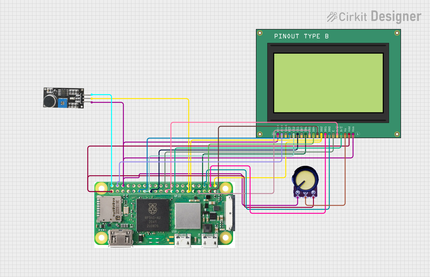
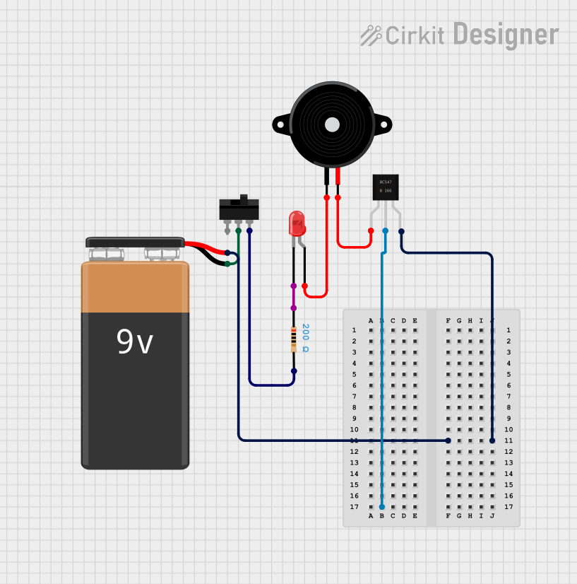
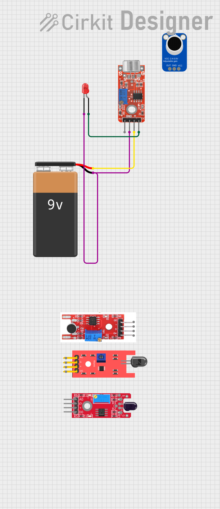
Explore Projects Built with Little Soundie
Common Applications and Use Cases
- Greeting cards with personalized voice messages
- Interactive art installations with sound effects
- Educational toys with audio feedback
- Prototyping for devices that require audio output
Technical Specifications
Key Technical Details
- Supply Voltage: 3.3V to 5.5V
- Output Power: 2W at 4Ω and 5V
- Audio Format: WAV files (16-bit, mono, up to 32 kHz sampling rate)
- Storage: Onboard 16MB flash memory
- Interface: UART (Serial)
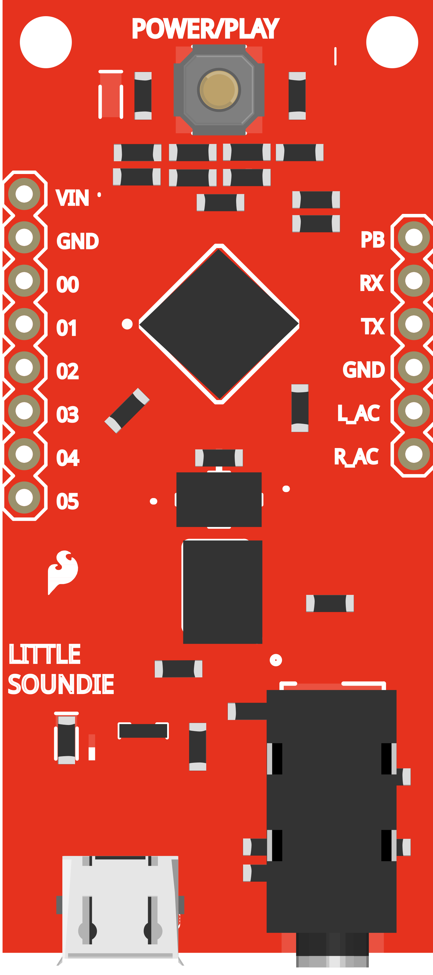
Pin Configuration and Descriptions
| Pin Number | Name | Description |
|---|---|---|
| 1 | VCC | Power supply (3.3V to 5.5V) |
| 2 | GND | Ground connection |
| 3 | RX | UART receive pin (connect to TX of the controller) |
| 4 | TX | UART transmit pin (connect to RX of the controller) |
| 5 | SPK+ | Positive speaker output |
| 6 | SPK- | Negative speaker output |
Usage Instructions
How to Use the Component in a Circuit
- Power Supply: Connect the VCC pin to a 3.3V to 5.5V power source and the GND pin to the ground.
- Speaker Connection: Attach a speaker to the SPK+ and SPK- pins. Ensure the speaker's impedance and power rating are compatible with the Little Soundie's output.
- Serial Communication: Connect the RX pin to the TX pin of your microcontroller (e.g., Arduino UNO) and the TX pin to the RX pin of the microcontroller.
- Audio Files: Load your WAV audio files onto the Little Soundie using the provided software tool.
Important Considerations and Best Practices
- Ensure that the power supply is within the specified voltage range to prevent damage.
- Use a speaker with an impedance of 4Ω to 8Ω for optimal performance.
- Keep the audio file size within the 16MB onboard storage limit.
- Avoid disconnecting the speaker while the module is powered to prevent damage to the amplifier.
Example Code for Arduino UNO
#include <SoftwareSerial.h>

SoftwareSerial soundieSerial(10, 11); // RX, TX

void setup() {
  soundieSerial.begin(9600); // Initialize serial communication with Little Soundie
  Serial.begin(9600); // Start serial communication with PC for debugging
}

void loop() {
  if (Serial.available()) { // Check if there is a command from the PC
    char command = Serial.read(); // Read the command
    soundieSerial.write(command); // Send the command to the Little Soundie
  }

  if (soundieSerial.available()) { // Check if there is a response from Little Soundie
    Serial.write(soundieSerial.read()); // Send the response to the PC
  }
}
Note: This example sets up a simple serial relay between the Arduino UNO and the Little Soundie, allowing commands to be sent from a PC to control the module.
Troubleshooting and FAQs
Common Issues Users Might Face
- No Sound Output: Ensure the speaker is properly connected and the audio file is correctly loaded onto the module.
- Distorted Sound: Check if the speaker specifications match the output power of the Little Soundie. Also, verify the audio file's quality and format.
- Module Not Responding: Confirm that the serial communication is correctly established and the power supply is within the specified range.
Solutions and Tips for Troubleshooting
- Double-check all connections, including power, ground, and speaker wires.
- Reload the audio files onto the Little Soundie to ensure they are not corrupted.
- Use a different power source if the current one is unstable or out of the specified voltage range.
FAQs
Q: Can I use a stereo speaker with the Little Soundie? A: The Little Soundie is designed for mono output. For stereo sound, you would need two modules or to mix the stereo signal into mono.
Q: How do I change the audio files on the Little Soundie? A: Use the provided software tool to upload new WAV files to the onboard flash memory.
Q: What is the maximum length of an audio file I can play? A: The maximum length depends on the file size and the available storage. With 16MB of memory, you can store approximately 16 minutes of audio at a 128 kbps bitrate.
Q: Can I control the playback volume? A: The Little Soundie does not have a built-in volume control. Volume adjustments must be made in the audio file itself or through an external amplifier with volume control.
For further assistance, please refer to the manufacturer's support resources or community forums dedicated to the Little Soundie module.