
How to Use 12V VOLTAGE DETECTOR: Examples, Pinouts, and Specs
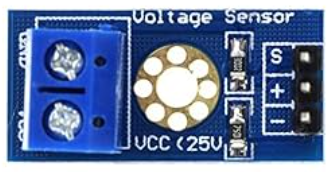
 Design with 12V VOLTAGE DETECTOR in Cirkit Designer
Introduction
The 12V Voltage Detector is an electronic device designed to monitor and indicate the presence of a 12V voltage level in a circuit. It is commonly used in automotive, industrial, and DIY electronics projects to ensure proper voltage levels for safety and performance checks. This component is particularly useful in systems where maintaining a stable 12V supply is critical, such as battery-powered devices, power distribution systems, and voltage monitoring circuits.
Explore Projects Built with 12V VOLTAGE DETECTOR
Explore Projects Built with 12V VOLTAGE DETECTOR
Common Applications:
- Automotive systems to monitor battery voltage
- Power supply monitoring in industrial equipment
- DIY electronics projects for voltage detection
- Safety circuits to prevent overvoltage or undervoltage conditions
Technical Specifications
The following table outlines the key technical details of the 12V Voltage Detector:
| Parameter | Value |
|---|---|
| Operating Voltage | 12V DC |
| Detection Voltage Range | 11.5V to 12.5V (typical) |
| Output Signal | Digital (High/Low) |
| Current Consumption | < 10mA |
| Output Voltage (High) | 5V (logic high) |
| Output Voltage (Low) | 0V (logic low) |
| Operating Temperature | -20°C to 70°C |
| Dimensions | 25mm x 15mm x 10mm |
Pin Configuration and Descriptions
The 12V Voltage Detector typically has three pins. The table below describes each pin:
| Pin | Name | Description |
|---|---|---|
| 1 | VCC | Connect to the 12V DC power supply |
| 2 | GND | Ground connection |
| 3 | OUT | Digital output pin (High when 12V is detected, Low otherwise) |
Usage Instructions
How to Use the 12V Voltage Detector in a Circuit
- Power Connection: Connect the
VCCpin to the 12V DC power supply and theGNDpin to the ground of the circuit. - Output Signal: Connect the
OUTpin to a microcontroller (e.g., Arduino) or an indicator (e.g., LED or buzzer) to monitor the voltage status. - Load Considerations: Ensure that the connected load does not exceed the current rating of the output pin.
Example Circuit with Arduino UNO
Below is an example of how to connect the 12V Voltage Detector to an Arduino UNO to monitor the voltage and display the status via the Serial Monitor.
Circuit Diagram:
VCC→ 12V power supplyGND→ Arduino GNDOUT→ Arduino digital pin 2
Arduino Code:
// 12V Voltage Detector Example with Arduino UNO
// This code reads the output of the 12V Voltage Detector and prints the status
// to the Serial Monitor.

const int voltageDetectorPin = 2; // Pin connected to the OUT pin of the detector

void setup() {
  pinMode(voltageDetectorPin, INPUT); // Set the pin as input
  Serial.begin(9600); // Initialize Serial communication at 9600 baud
}

void loop() {
  int voltageStatus = digitalRead(voltageDetectorPin); // Read the detector output

  if (voltageStatus == HIGH) {
    // If HIGH, 12V is detected
    Serial.println("12V Detected");
  } else {
    // If LOW, 12V is not detected
    Serial.println("12V Not Detected");
  }

  delay(500); // Wait for 500ms before the next reading
}
Important Considerations and Best Practices
- Voltage Range: Ensure the input voltage is within the specified range (11.5V to 12.5V). Exceeding this range may damage the detector.
- Output Signal: The output pin provides a digital signal. Use a pull-down resistor if necessary to stabilize the signal.
- Temperature: Operate the detector within the specified temperature range to avoid performance degradation.
Troubleshooting and FAQs
Common Issues and Solutions
No Output Signal:
- Cause: Incorrect wiring or insufficient input voltage.
- Solution: Verify the connections and ensure the input voltage is within the specified range.
Output Always Low:
- Cause: Input voltage is below the detection threshold.
- Solution: Check the input voltage and ensure it is at least 11.5V.
Output Always High:
- Cause: Faulty detector or excessive noise in the circuit.
- Solution: Test the detector with a stable 12V source and add decoupling capacitors if noise is present.
Intermittent Output:
- Cause: Loose connections or unstable power supply.
- Solution: Secure all connections and use a regulated power supply.
FAQs
Q1: Can the 12V Voltage Detector work with voltages higher than 12V?
A1: No, the detector is designed specifically for 12V systems. Using higher voltages may damage the component.
Q2: Can I use the detector with a 3.3V microcontroller?
A2: Yes, but you may need a level shifter to safely interface the 5V output signal with the 3.3V logic level.
Q3: What happens if the input voltage drops below 11.5V?
A3: The output pin will go LOW, indicating that the voltage is below the detection threshold.
Q4: Is the detector polarity-sensitive?
A4: Yes, ensure that the VCC and GND pins are connected correctly to avoid damage.
By following this documentation, you can effectively integrate the 12V Voltage Detector into your projects for reliable voltage monitoring.