
How to Use esp32 r1 d32: Examples, Pinouts, and Specs
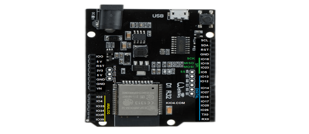
 Design with esp32 r1 d32 in Cirkit Designer
Introduction
The ESP32 R1 D32, manufactured by Burhan Butt, is a powerful and versatile microcontroller module designed for IoT (Internet of Things) applications. It features dual-core processing, integrated Wi-Fi, and Bluetooth capabilities, making it ideal for a wide range of wireless communication and control tasks. With its compact design and robust performance, the ESP32 R1 D32 is suitable for both hobbyist projects and professional applications.
Explore Projects Built with esp32 r1 d32
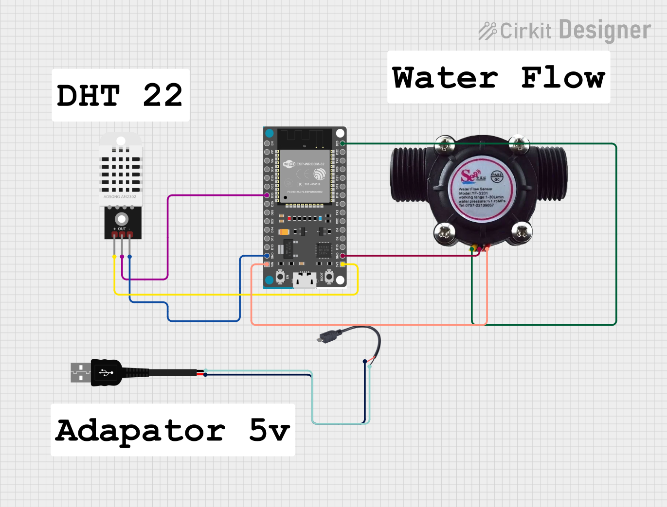 Open Project in Cirkit Designer
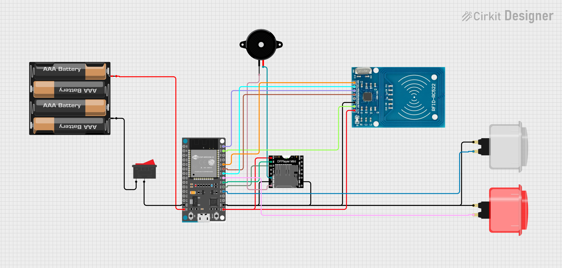 Open Project in Cirkit Designer
 Open Project in Cirkit Designer
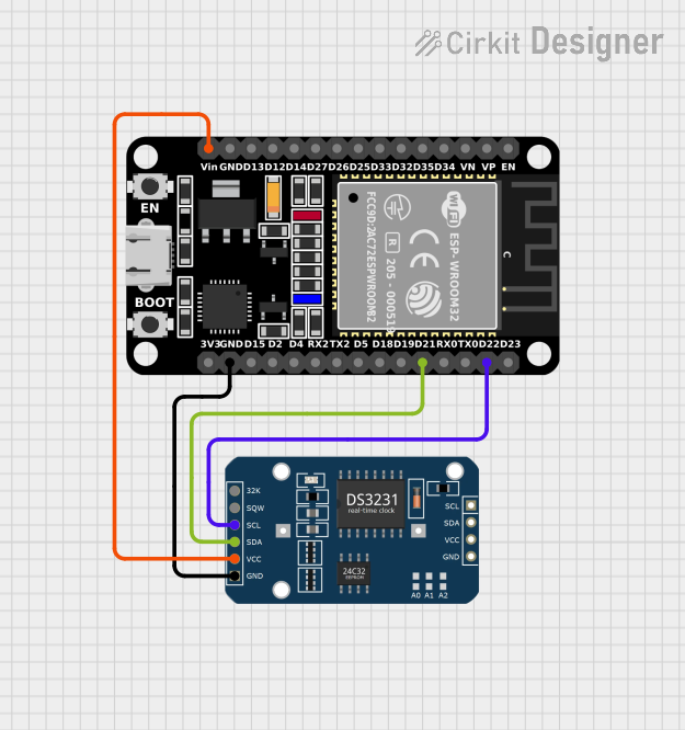 Open Project in Cirkit Designer
Explore Projects Built with esp32 r1 d32
Open Project in Cirkit DesignerOpen Project in Cirkit DesignerOpen Project in Cirkit DesignerOpen Project in Cirkit DesignerCommon Applications and Use Cases
- Home automation systems
- Wireless sensor networks
- IoT devices and smart appliances
- Wearable technology
- Robotics and automation
- Data logging and remote monitoring
Technical Specifications
The following table outlines the key technical details of the ESP32 R1 D32:
| Parameter | Specification |
|---|---|
| Manufacturer | Burhan Butt |
| Part ID | ESP32 R1 D32 |
| Microcontroller | Tensilica Xtensa Dual-Core 32-bit LX6 |
| Operating Voltage | 3.3V |
| Input Voltage (VIN) | 5V |
| Flash Memory | 4MB |
| SRAM | 520KB |
| Wi-Fi Standard | 802.11 b/g/n |
| Bluetooth Version | v4.2 BR/EDR and BLE |
| GPIO Pins | 34 |
| ADC Channels | 18 |
| DAC Channels | 2 |
| PWM Channels | 16 |
| Communication Interfaces | UART, SPI, I2C, I2S, CAN, Ethernet |
| Operating Temperature | -40°C to +85°C |
| Dimensions | 25.5mm x 51mm |
Pin Configuration and Descriptions
The ESP32 R1 D32 has a total of 38 pins. Below is a summary of the pin configuration:
| Pin Name | Type | Description |
|---|---|---|
| VIN | Power Input | Input voltage (5V) for powering the module. |
| GND | Power Ground | Ground connection. |
| 3V3 | Power Output | Regulated 3.3V output. |
| EN | Input | Enable pin; active high to enable the module. |
| IO0 | GPIO/Boot Mode | General-purpose I/O or boot mode selection. |
| IO2 | GPIO | General-purpose I/O. |
| IO4 | GPIO | General-purpose I/O. |
| IO5 | GPIO | General-purpose I/O. |
| IO12 | GPIO/ADC | General-purpose I/O or ADC input. |
| IO13 | GPIO/ADC | General-purpose I/O or ADC input. |
| IO14 | GPIO/ADC | General-purpose I/O or ADC input. |
| IO15 | GPIO/ADC | General-purpose I/O or ADC input. |
| IO16 | GPIO | General-purpose I/O. |
| IO17 | GPIO | General-purpose I/O. |
| IO18 | GPIO/SPI | General-purpose I/O or SPI interface. |
| IO19 | GPIO/SPI | General-purpose I/O or SPI interface. |
| IO21 | GPIO/I2C | General-purpose I/O or I2C SDA. |
| IO22 | GPIO/I2C | General-purpose I/O or I2C SCL. |
| IO23 | GPIO/SPI | General-purpose I/O or SPI interface. |
| IO25 | GPIO/DAC | General-purpose I/O or DAC output. |
| IO26 | GPIO/DAC | General-purpose I/O or DAC output. |
| IO27 | GPIO | General-purpose I/O. |
| IO32 | GPIO/ADC | General-purpose I/O or ADC input. |
| IO33 | GPIO/ADC | General-purpose I/O or ADC input. |
| IO34 | GPIO/ADC | General-purpose I/O or ADC input (input only). |
| IO35 | GPIO/ADC | General-purpose I/O or ADC input (input only). |
Usage Instructions
How to Use the ESP32 R1 D32 in a Circuit
Powering the Module:
- Connect the VIN pin to a 5V power source or use the micro-USB port for power.
- Ensure the GND pin is connected to the ground of your circuit.
Programming the Module:
- Use the Arduino IDE or ESP-IDF (Espressif IoT Development Framework) to program the ESP32 R1 D32.
- Install the necessary board definitions and drivers for the ESP32 in your development environment.
Connecting Peripherals:
- Use the GPIO pins to connect sensors, actuators, or other peripherals.
- For analog inputs, connect sensors to the ADC pins (e.g., IO32, IO33).
- For PWM outputs, use any of the GPIO pins configured for PWM.
Wi-Fi and Bluetooth Setup:
- Use the built-in Wi-Fi and Bluetooth libraries to configure wireless communication.
Important Considerations and Best Practices
- Always use a level shifter when interfacing the ESP32 with 5V logic devices.
- Avoid exceeding the maximum current rating of the GPIO pins (12mA per pin).
- Use decoupling capacitors near the power pins to reduce noise and improve stability.
- Ensure proper grounding to avoid communication issues or erratic behavior.
Example Code for Arduino UNO Integration
Below is an example of how to use the ESP32 R1 D32 with an Arduino UNO to blink an LED:
// Example: Blink an LED connected to GPIO2 on the ESP32 R1 D32

#define LED_PIN 2  // Define the GPIO pin for the LED

void setup() {
  pinMode(LED_PIN, OUTPUT);  // Set the LED pin as an output
}

void loop() {
  digitalWrite(LED_PIN, HIGH);  // Turn the LED on
  delay(1000);                  // Wait for 1 second
  digitalWrite(LED_PIN, LOW);   // Turn the LED off
  delay(1000);                  // Wait for 1 second
}
Troubleshooting and FAQs
Common Issues and Solutions
ESP32 Not Detected by Computer:
- Ensure the correct drivers for the ESP32 are installed.
- Check the USB cable for faults or try a different cable.
Wi-Fi Connection Fails:
- Verify the SSID and password in your code.
- Ensure the Wi-Fi network is within range and not overloaded.
Program Upload Fails:
- Press and hold the BOOT button while uploading the code.
- Check the selected board and port in the Arduino IDE.
GPIO Pins Not Responding:
- Ensure the pins are not being used for other functions (e.g., boot mode).
- Verify the pinMode configuration in your code.
FAQs
Q: Can the ESP32 R1 D32 operate on battery power?
A: Yes, the module can be powered using a 3.7V LiPo battery connected to the VIN pin.
Q: What is the maximum Wi-Fi range of the ESP32 R1 D32?
A: The Wi-Fi range is approximately 50 meters indoors and up to 200 meters outdoors, depending on environmental factors.
Q: Can I use the ESP32 R1 D32 with MicroPython?
A: Yes, the ESP32 R1 D32 supports MicroPython. You can flash the MicroPython firmware to the module and use it for development.
Q: How do I reset the ESP32 R1 D32?
A: Press the EN (enable) button on the module to reset it.
This concludes the documentation for the ESP32 R1 D32. For further assistance, refer to the official datasheet or community forums.