How to Use ESP8266 LoLin NodeMCU V3: Examples, Pinouts, and Specs
Introduction
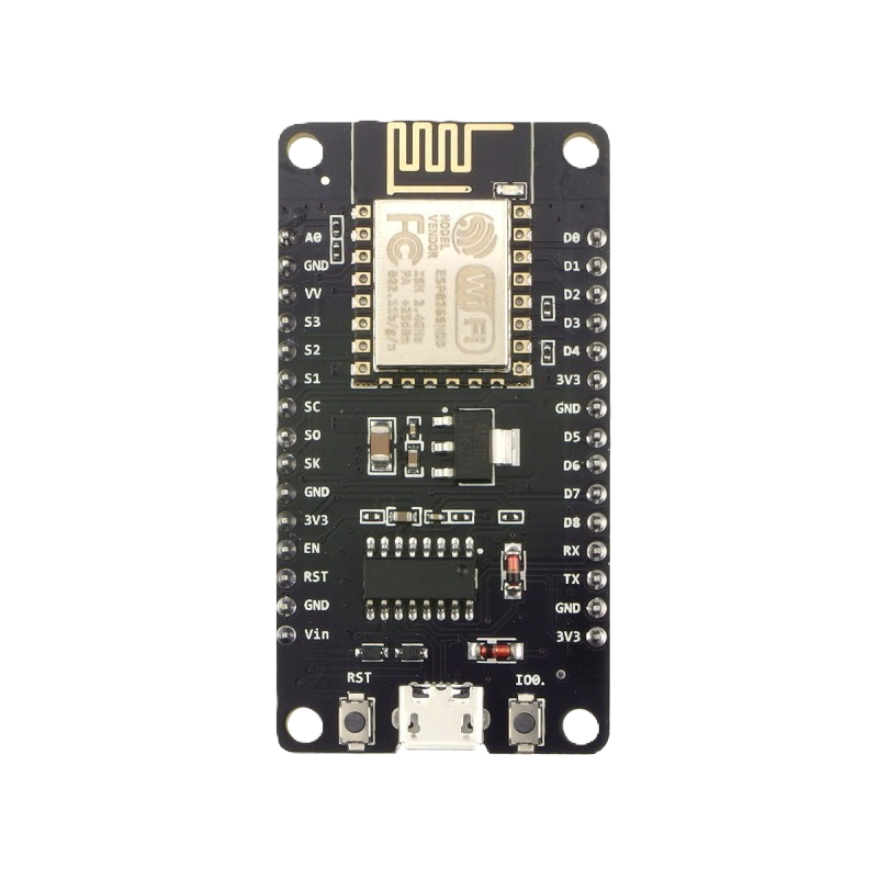
The ESP8266 LoLin NodeMCU V3 is a low-cost Wi-Fi microcontroller board based on the ESP8266 chip. It features a built-in USB interface for easy programming and a variety of GPIO pins for connecting sensors, actuators, and other devices. This board is widely used in IoT (Internet of Things) applications due to its affordability, compact size, and robust wireless capabilities.
Explore Projects Built with ESP8266 LoLin NodeMCU V3
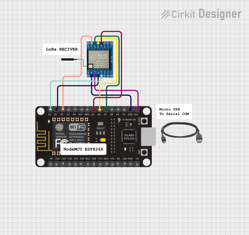
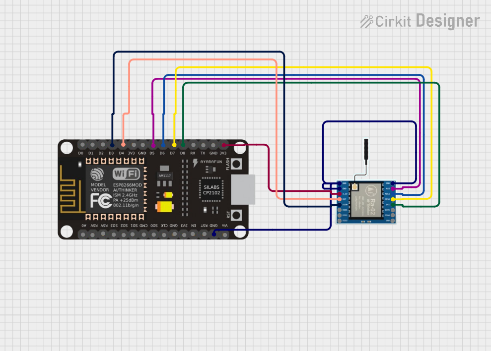

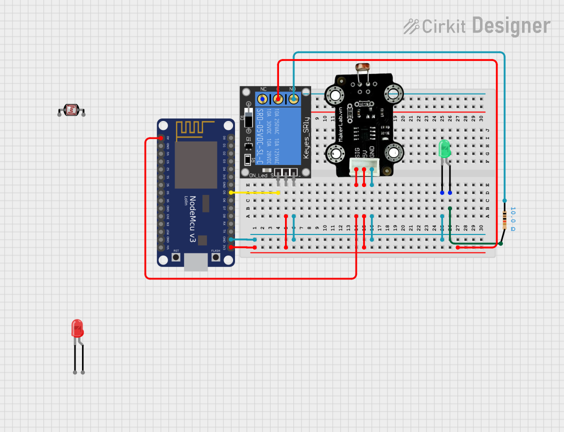
Explore Projects Built with ESP8266 LoLin NodeMCU V3
Common Applications and Use Cases
- Home automation systems
- IoT devices and smart appliances
- Wireless sensor networks
- Remote data logging and monitoring
- Prototyping Wi-Fi-enabled projects
Technical Specifications
Key Technical Details
| Specification | Value |
|---|---|
| Microcontroller | ESP8266 |
| Operating Voltage | 3.3V |
| Input Voltage (via USB) | 5V |
| Flash Memory | 4MB |
| Clock Speed | 80 MHz / 160 MHz |
| Wi-Fi Standard | 802.11 b/g/n |
| GPIO Pins | 11 (Digital I/O) |
| Analog Input Pin | 1 (10-bit ADC, 0–3.3V range) |
| USB Interface | CH340G USB-to-Serial Converter |
| Dimensions | 58mm x 31mm x 13mm |
Pin Configuration and Descriptions
| Pin Name | Description |
|---|---|
| VIN | Input voltage pin (5V input from USB or external power source). |
| 3V3 | Regulated 3.3V output from the onboard voltage regulator. |
| GND | Ground pin. |
| D0–D8 | General-purpose digital I/O pins. Can be used for input or output. |
| A0 | Analog input pin (0–3.3V range, 10-bit resolution). |
| RX | UART receive pin for serial communication. |
| TX | UART transmit pin for serial communication. |
| EN | Enable pin. Pull HIGH to enable the chip, LOW to disable it. |
| RST | Reset pin. Pull LOW to reset the board. |
| SDA | I2C data pin (shared with GPIO4 by default). |
| SCL | I2C clock pin (shared with GPIO5 by default). |
Usage Instructions
How to Use the ESP8266 LoLin NodeMCU V3 in a Circuit
Powering the Board:
- Connect the board to your computer or a USB power source using a micro-USB cable.
- Alternatively, supply 5V to the VIN pin and GND pin for external power.
Programming the Board:
- Install the Arduino IDE and add the ESP8266 board package via the Board Manager.
- Select "NodeMCU 1.0 (ESP-12E Module)" as the board in the Arduino IDE.
- Connect the board to your computer and select the appropriate COM port.
- Write your code and upload it to the board.
Connecting Sensors and Actuators:
- Use the GPIO pins (D0–D8) for digital input/output.
- Use the A0 pin for analog input (ensure the input voltage does not exceed 3.3V).
- For I2C devices, connect SDA to GPIO4 and SCL to GPIO5 by default.
Wi-Fi Configuration:
- Use the ESP8266WiFi library in the Arduino IDE to connect the board to a Wi-Fi network.
- Example code for connecting to Wi-Fi is provided below.
Important Considerations and Best Practices
- Voltage Levels: Ensure all connected devices operate at 3.3V logic levels. Use level shifters if necessary.
- Power Supply: Avoid powering high-current devices directly from the board. Use an external power source.
- GPIO Limitations: Some GPIO pins (e.g., D3, D4) have specific boot modes and should not be pulled HIGH or LOW during startup.
- Heat Management: The ESP8266 chip may heat up during operation. Ensure proper ventilation.
Example Code: Connecting to Wi-Fi
#include <ESP8266WiFi.h> // Include the ESP8266 Wi-Fi library

const char* ssid = "Your_SSID";       // Replace with your Wi-Fi network name
const char* password = "Your_Password"; // Replace with your Wi-Fi password

void setup() {
  Serial.begin(115200); // Start serial communication at 115200 baud
  WiFi.begin(ssid, password); // Connect to the Wi-Fi network

  Serial.print("Connecting to Wi-Fi");
  while (WiFi.status() != WL_CONNECTED) {
    delay(500); // Wait for connection
    Serial.print(".");
  }
  Serial.println("\nConnected to Wi-Fi!");
  Serial.print("IP Address: ");
  Serial.println(WiFi.localIP()); // Print the assigned IP address
}

void loop() {
  // Add your main code here
}
Troubleshooting and FAQs
Common Issues and Solutions
The board is not detected by the computer:
- Ensure the correct USB drivers (CH340G) are installed on your computer.
- Try using a different USB cable or port.
Upload errors in the Arduino IDE:
- Check that the correct board and COM port are selected in the Arduino IDE.
- Press and hold the "Flash" button on the board while uploading the code.
Wi-Fi connection issues:
- Double-check the SSID and password in your code.
- Ensure the Wi-Fi network is within range and not using unsupported security protocols.
GPIO pins not working as expected:
- Verify that the pins are not being used for other functions (e.g., boot modes).
- Check for loose or incorrect connections in your circuit.
FAQs
Can I power the board with a 3.7V LiPo battery?
Yes, connect the battery to the VIN and GND pins. Ensure the battery voltage is regulated.What is the maximum current the GPIO pins can handle?
Each GPIO pin can source or sink up to 12mA. Avoid exceeding this limit.Can I use the board as a standalone web server?
Yes, the ESP8266 can host a web server using the ESP8266WebServer library.How do I reset the board?
Press the "RST" button or pull the RST pin LOW momentarily to reset the board.