Cirkit Designer
Your all-in-one circuit design IDE
Home /
Component Documentation
How to Use Teensy_3_1 XBee Adapter: Examples, Pinouts, and Specs
Introduction
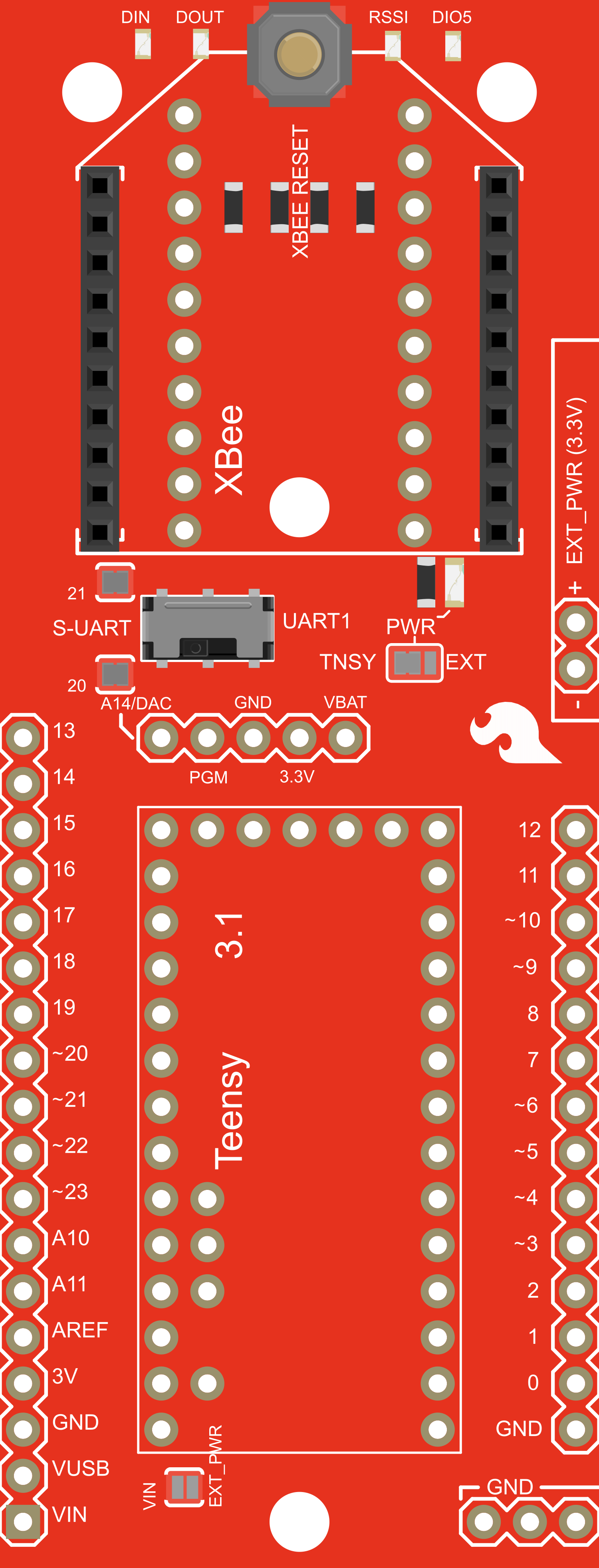
The Teensy 3.1 XBee Adapter is a versatile breakout board that facilitates the integration of a Teensy 3.1 microcontroller with an XBee wireless module. This adapter is designed to streamline the process of establishing a wireless communication link for your projects. It is commonly used in applications such as remote sensor networks, home automation, and robotics.
Explore Projects Built with Teensy_3_1 XBee Adapter
Arduino Nano-Based Wireless Motion Detection System with ADXL335 Accelerometer and NRF24L01 Transceiver
This circuit features an Arduino Nano interfaced with an ADXL335 accelerometer and an NRF24L01 wireless communication module. The Arduino is powered by a 9V battery and reads the X and Y-axis outputs from the accelerometer, potentially to transmit this data wirelessly via the NRF24L01. The NRF24L01 is connected to the Arduino's SPI pins for communication and its VCC is connected to the Arduino's 3.3V output.
Arduino Nano Wireless Communication System with nRF24L01 Module

This circuit connects an nRF24L01 wireless transceiver module to an Arduino Nano microcontroller through an adapter board. The Arduino Nano is configured to communicate with the nRF24L01 via SPI (Serial Peripheral Interface), using pins D9 and D10 for chip enable (CE) and chip select (CSN), and pins D11 to D13 for the SPI bus (MOSI, MISO, SCK). An electrolytic capacitor is connected across the power supply lines likely for power stabilization.
Arduino Nano and NRF24L01 Wireless Communication Module
This circuit features an Arduino Nano microcontroller interfaced with an NRF24L01 wireless transceiver module via an adapter. The setup is designed for wireless communication, with the Arduino controlling the transceiver through SPI and digital I/O pins, and the code provided is a basic template for further development.
STM32F103C8T6 Bluetooth-Controlled Arcade Joystick Interface

This circuit features an STM32F103C8T6 microcontroller interfaced with a Bluetooth HC-06 module for wireless communication and an Adafruit Arcade Joystick for user input. The microcontroller's pins B0 and B10 are connected to the TXD and RXD pins of the Bluetooth module, enabling serial communication, while pins B14 and B15 interface with the joystick's directional controls. The circuit is powered by a battery, with power distribution managed through the microcontroller's 3.3V pin and common ground connections.
Explore Projects Built with Teensy_3_1 XBee Adapter
Arduino Nano-Based Wireless Motion Detection System with ADXL335 Accelerometer and NRF24L01 Transceiver
This circuit features an Arduino Nano interfaced with an ADXL335 accelerometer and an NRF24L01 wireless communication module. The Arduino is powered by a 9V battery and reads the X and Y-axis outputs from the accelerometer, potentially to transmit this data wirelessly via the NRF24L01. The NRF24L01 is connected to the Arduino's SPI pins for communication and its VCC is connected to the Arduino's 3.3V output.
Arduino Nano Wireless Communication System with nRF24L01 Module
This circuit connects an nRF24L01 wireless transceiver module to an Arduino Nano microcontroller through an adapter board. The Arduino Nano is configured to communicate with the nRF24L01 via SPI (Serial Peripheral Interface), using pins D9 and D10 for chip enable (CE) and chip select (CSN), and pins D11 to D13 for the SPI bus (MOSI, MISO, SCK). An electrolytic capacitor is connected across the power supply lines likely for power stabilization.
Arduino Nano and NRF24L01 Wireless Communication Module
This circuit features an Arduino Nano microcontroller interfaced with an NRF24L01 wireless transceiver module via an adapter. The setup is designed for wireless communication, with the Arduino controlling the transceiver through SPI and digital I/O pins, and the code provided is a basic template for further development.
STM32F103C8T6 Bluetooth-Controlled Arcade Joystick Interface
This circuit features an STM32F103C8T6 microcontroller interfaced with a Bluetooth HC-06 module for wireless communication and an Adafruit Arcade Joystick for user input. The microcontroller's pins B0 and B10 are connected to the TXD and RXD pins of the Bluetooth module, enabling serial communication, while pins B14 and B15 interface with the joystick's directional controls. The circuit is powered by a battery, with power distribution managed through the microcontroller's 3.3V pin and common ground connections.
Technical Specifications
Key Technical Details
- Compatibility: Designed for use with Teensy 3.1 microcontroller
- Voltage Support: 3.3V and 5V logic levels
- Current Rating: Dependent on the XBee module used
- Dimensions: Matches the Teensy 3.1 footprint
Pin Configuration and Descriptions
| Pin Number | Description | Teensy 3.1 Connection | XBee Connection |
|---|---|---|---|
| 1 | 3.3V Power Supply | 3.3V | VCC |
| 2 | 5V Power Supply (optional) | VIN | - |
| 3 | Ground | GND | GND |
| 4 | Transmit Data (TX) | Pin 1 (TX) | DIN |
| 5 | Receive Data (RX) | Pin 0 (RX) | DOUT |
| 6 | Request To Send (RTS) | - | RTS |
| 7 | Clear To Send (CTS) | - | CTS |
| 8 | Sleep Request (optional) | - | SLEEP_RQ |
| 9 | Associate Indicator (optional) | - | ASSOC |
| 10 | On/Sleep Indicator (optional) | - | ON/SLEEP |
Usage Instructions
Integrating with a Circuit
- Powering the Adapter: Connect the 3.3V pin on the Teensy 3.1 to the 3.3V pin on the adapter. If 5V logic is required, connect the VIN pin on the Teensy to the 5V supply pin on the adapter.
- Data Communication: Connect the TX and RX pins on the Teensy to the adapter's corresponding TX and RX pins to establish serial communication with the XBee module.
- Optional Control Lines: If using RTS/CTS for flow control or other optional signals, connect these pins between the Teensy and the adapter as needed.
Important Considerations and Best Practices
- Voltage Levels: Ensure that the logic level of the XBee module matches the Teensy 3.1 to prevent damage.
- Antenna Placement: Keep the antenna area of the XBee module clear of metal objects to avoid signal interference.
- Firmware Configuration: Configure the XBee module with the appropriate firmware for your application before integrating it with the Teensy 3.1.
Troubleshooting and FAQs
Common Issues
- Communication Failure: Check the serial connection between the Teensy and the XBee adapter. Ensure that the TX and RX pins are correctly connected.
- Power Issues: Verify that the adapter is receiving the correct voltage and that the power connections are secure.
- Signal Interference: If experiencing erratic behavior, check for potential sources of electromagnetic interference near the XBee antenna.
Solutions and Tips
- Serial Connection: Use a serial monitor to test the communication between the Teensy and the XBee module.
- XBee Configuration: Utilize the XBee configuration software (XCTU) to check and update the XBee module settings.
- Antenna Orientation: Adjust the orientation of the XBee antenna to improve signal strength and reliability.
Example Code for Arduino UNO
#include <SoftwareSerial.h>

// Define the RX and TX pins connected to the XBee
#define XBEE_RX 10
#define XBEE_TX 11

// Set up the software serial port
SoftwareSerial xbeeSerial(XBEE_RX, XBEE_TX);

void setup() {
  // Begin serial communication with the XBee at 9600 baud
  xbeeSerial.begin(9600);
}

void loop() {
  // Check if data is available to read from the XBee
  if (xbeeSerial.available()) {
    // Read the incoming byte from the XBee
    char incomingByte = xbeeSerial.read();
    // TODO: Handle the incoming data as required
  }

  // Check if data needs to be sent to the XBee
  // TODO: Send data using xbeeSerial.write() or xbeeSerial.print()
}
Note: The example code provided is for an Arduino UNO and is intended to illustrate basic communication with an XBee module. For the Teensy 3.1, the hardware serial ports should be used instead of SoftwareSerial, and the pin definitions will differ. Adjust the code accordingly for the Teensy 3.1 platform.