How to Use ESP dev module: Examples, Pinouts, and Specs
Introduction
The ESP Dev Module is a development board based on the ESP8266 or ESP32 microcontroller, designed for creating Internet of Things (IoT) applications. It features built-in Wi-Fi connectivity, making it ideal for wireless communication projects. The module includes General Purpose Input/Output (GPIO) pins, an Analog-to-Digital Converter (ADC), and often integrates a USB interface for easy programming and debugging. Its compact size and versatility make it a popular choice for hobbyists and professionals alike.
Explore Projects Built with ESP dev module


Explore Projects Built with ESP dev module
Common Applications and Use Cases
- Home automation systems
- Wireless sensor networks
- Smart appliances
- IoT prototyping and development
- Remote monitoring and control
- Data logging and cloud integration
Technical Specifications
Key Technical Details
| Specification | ESP8266 Dev Module | ESP32 Dev Module |
|---|---|---|
| Microcontroller | ESP8266 | ESP32 |
| Clock Speed | 80 MHz (up to 160 MHz) | 160 MHz (up to 240 MHz) |
| Flash Memory | 4 MB (varies by model) | 4 MB (varies by model) |
| RAM | 50 KB | 520 KB |
| Wi-Fi Standard | 802.11 b/g/n | 802.11 b/g/n |
| GPIO Pins | Up to 17 | Up to 36 |
| ADC Resolution | 10-bit | 12-bit |
| Operating Voltage | 3.3V | 3.3V |
| USB Interface | Integrated | Integrated |
| Power Consumption | Low power (varies by mode) | Ultra-low power (varies by mode) |
Pin Configuration and Descriptions
ESP8266 Dev Module
| Pin Name | Description |
|---|---|
| GPIO0 | General-purpose I/O, boot mode select |
| GPIO2 | General-purpose I/O |
| GPIO15 | General-purpose I/O, boot mode select |
| ADC (A0) | Analog input (0–1V) |
| GND | Ground |
| 3V3 | 3.3V power supply |
| EN | Chip enable (active high) |
| TX | UART transmit |
| RX | UART receive |
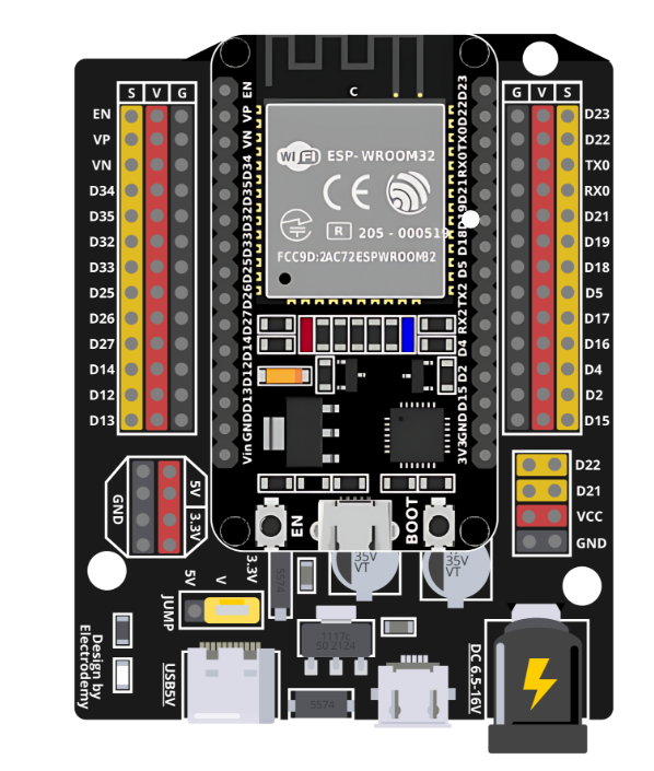
ESP32 Dev Module
| Pin Name | Description |
|---|---|
| GPIO0 | General-purpose I/O, boot mode select |
| GPIO2 | General-purpose I/O |
| GPIO36 | Analog input (ADC1_CH0) |
| GPIO39 | Analog input (ADC1_CH3) |
| GND | Ground |
| 3V3 | 3.3V power supply |
| EN | Chip enable (active high) |
| TX0 | UART0 transmit |
| RX0 | UART0 receive |
Usage Instructions
How to Use the Component in a Circuit
- Power Supply: Connect the 3V3 pin to a 3.3V power source and GND to ground. Avoid exceeding the voltage limit to prevent damage.
- Programming: Use a USB cable to connect the module to your computer. Install the necessary drivers (e.g., CP2102 or CH340) if required.
- GPIO Usage: Connect peripherals (e.g., LEDs, sensors) to the GPIO pins. Use appropriate resistors to limit current.
- Wi-Fi Configuration: Use the built-in Wi-Fi to connect to a network. Configure the SSID and password in your code.
- Analog Input: For ESP8266, ensure the input voltage to the ADC (A0) does not exceed 1V. For ESP32, use the ADC pins with a maximum input of 3.3V.
Important Considerations and Best Practices
- Voltage Levels: Ensure all connected devices operate at 3.3V logic levels. Use level shifters if interfacing with 5V devices.
- Boot Mode: For ESP8266, ensure GPIO0 is pulled low during boot for programming mode. For ESP32, this is handled automatically.
- Heat Management: The module may heat up during operation. Ensure proper ventilation or heat dissipation if used in enclosed spaces.
- Firmware Updates: Keep the firmware updated to ensure compatibility and security.
Example Code for Arduino UNO Integration
Below is an example of using the ESP Dev Module with an Arduino IDE to connect to a Wi-Fi network and print the IP address:
#include <ESP8266WiFi.h> // Use <WiFi.h> for ESP32

// Replace with your network credentials
const char* ssid = "Your_SSID";
const char* password = "Your_PASSWORD";

void setup() {
  Serial.begin(115200); // Initialize serial communication
  delay(10);

  // Connect to Wi-Fi
  Serial.println("Connecting to Wi-Fi...");
  WiFi.begin(ssid, password);

  while (WiFi.status() != WL_CONNECTED) {
    delay(1000); // Wait for connection
    Serial.print(".");
  }

  Serial.println("\nWi-Fi connected!");
  Serial.print("IP Address: ");
  Serial.println(WiFi.localIP()); // Print the IP address
}

void loop() {
  // Add your main code here
}
Troubleshooting and FAQs
Common Issues and Solutions
Module Not Detected by Computer:
- Ensure the USB cable is functional and supports data transfer.
- Install the correct USB-to-serial driver (e.g., CP2102 or CH340).
Wi-Fi Connection Fails:
- Double-check the SSID and password in your code.
- Ensure the Wi-Fi network is within range and operational.
GPIO Pins Not Responding:
- Verify the pin mode is correctly set in your code (e.g.,
pinMode(pin, OUTPUT)). - Check for short circuits or incorrect wiring.
- Verify the pin mode is correctly set in your code (e.g.,
ADC Reading Incorrect Values:
- For ESP8266, ensure the input voltage to A0 does not exceed 1V.
- For ESP32, confirm the ADC pin is correctly configured and within the 3.3V range.
FAQs
Q: Can I power the ESP Dev Module with 5V?
A: No, the module operates at 3.3V. Use a voltage regulator or level shifter if interfacing with 5V systems.
Q: How do I reset the module?
A: Press the reset button on the module or toggle the EN pin.
Q: Can I use the module without Wi-Fi?
A: Yes, the module can function as a standalone microcontroller for non-Wi-Fi applications.
Q: How do I update the firmware?
A: Use the ESP Flash Download Tool or the Arduino IDE to upload new firmware. Ensure the module is in boot mode during the process.