How to Use PNP Transistor (EBC): Examples, Pinouts, and Specs

Introduction
A PNP transistor is a type of bipolar junction transistor (BJT) characterized by its ability to amplify electronic signals. Unlike its NPN counterpart, the PNP transistor turns on when a small current flows through the base to the emitter. In the EBC (Emitter-Base-Collector) configuration, the emitter terminal is connected to the base terminal through a resistor, which is essential for controlling the base current and thus the overall transistor operation. PNP transistors are commonly used in switching and amplification applications, such as in audio amplifiers, signal processing, and power management circuits.
Explore Projects Built with PNP Transistor (EBC)
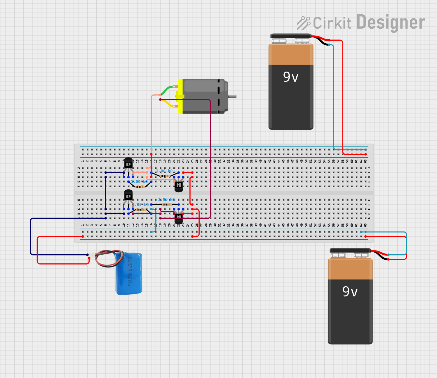
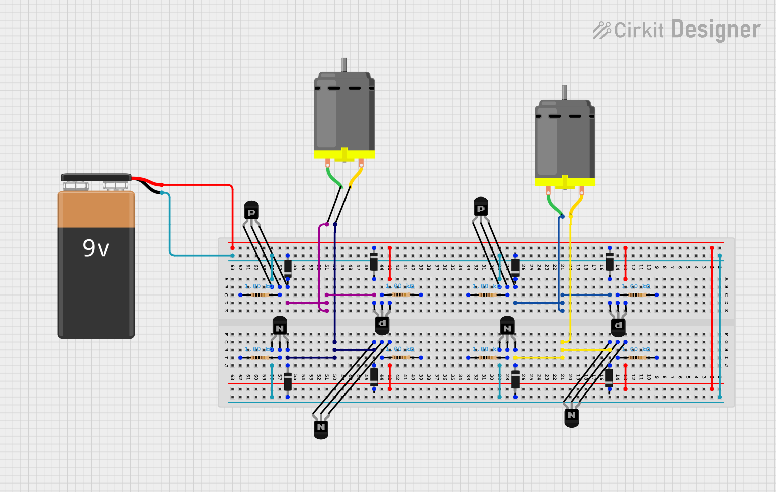

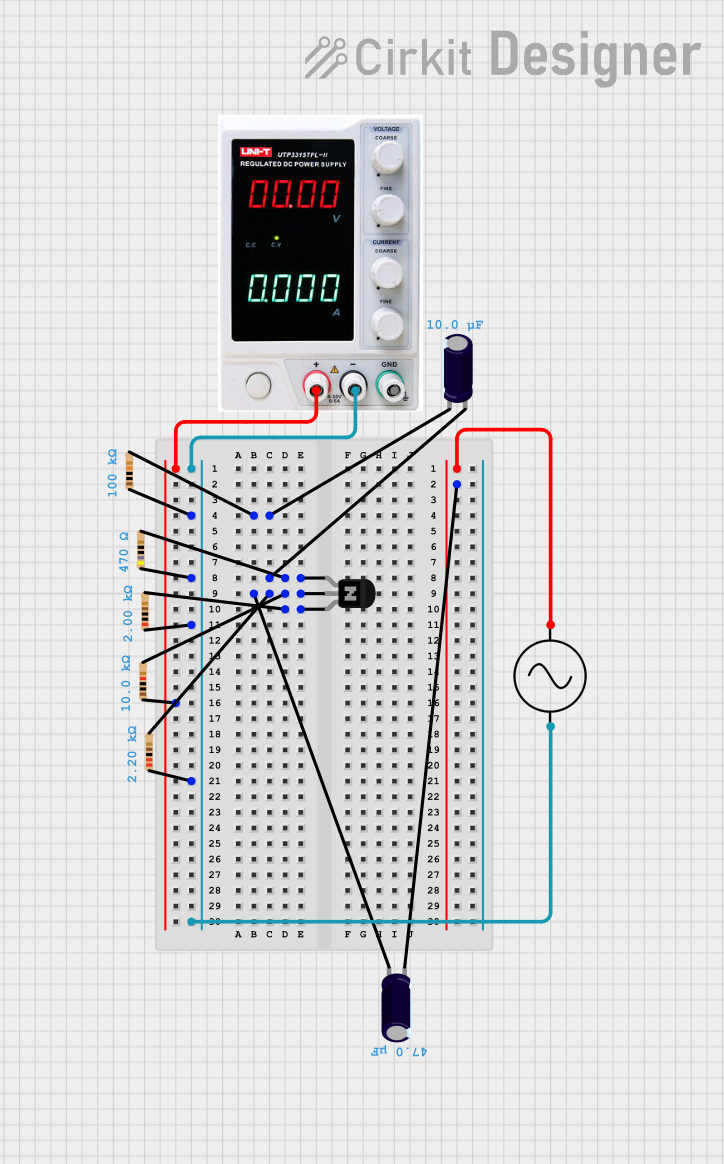
Explore Projects Built with PNP Transistor (EBC)
Technical Specifications
Key Technical Details
- Type: PNP Bipolar Junction Transistor
- Maximum Collector-Emitter Voltage (Vce): Specified by manufacturer (e.g., -30V)
- Maximum Collector Current (Ic): Specified by manufacturer (e.g., -100mA)
- Maximum Base Current (Ib): Specified by manufacturer (e.g., -5mA)
- Power Dissipation (Pd): Specified by manufacturer (e.g., 625mW)
- Transition Frequency (ft): Specified by manufacturer (e.g., 100MHz)
Pin Configuration and Descriptions
| Pin Number | Name | Description |
|---|---|---|
| 1 | Emitter | The current output of the transistor. |
| 2 | Base | Controls the transistor's operation. |
| 3 | Collector | The current input of the transistor. |
Usage Instructions
How to Use the PNP Transistor in a Circuit
- Identify the Pins: Refer to the datasheet to correctly identify the emitter, base, and collector pins.
- Base Resistor Selection: Choose a resistor for the base to limit the current. The value can be calculated using Ohm's law:
R = V / I, whereVis the voltage difference between the base and emitter, andIis the desired base current. - Circuit Connection: Connect the emitter to the positive voltage supply. The collector should be connected to the negative side of the load you wish to control.
- Signal Input: Apply a small current to the base to control the larger current flowing from the emitter to the collector.
Important Considerations and Best Practices
- Polarity: Ensure that the power supply and signals are correctly oriented to match the PNP transistor's polarity.
- Heat Dissipation: Use a heatsink if the transistor is expected to dissipate significant power.
- Saturation and Cutoff: To fully turn on the transistor (saturation), the base-emitter voltage should be higher than the base-collector voltage. To turn it off (cutoff), the base-emitter voltage should be zero or negative.
Troubleshooting and FAQs
Common Issues
- Transistor Not Switching: Check if the base current is sufficient to drive the transistor into saturation.
- Excessive Heat: Ensure the power dissipation does not exceed the transistor's rating. Check for short circuits.
Solutions and Tips for Troubleshooting
- Base Resistor Value: If the transistor is not turning on, try reducing the base resistor value.
- Check Connections: Verify that all connections are secure and that there are no solder bridges or open circuits.
FAQs
Q: Can I use a PNP transistor to switch a high current load? A: Yes, but ensure the transistor's current and power ratings are not exceeded, and use a heatsink if necessary.
Q: How do I know if my PNP transistor is working? A: Measure the voltage across the collector and emitter. When the transistor is on, the voltage should be low.
Example Code for Arduino UNO
Below is an example of how to use a PNP transistor to control an LED with an Arduino UNO.
// Define the pin connected to the base of the transistor
const int basePin = 2;

void setup() {
  // Set the base pin as an output
  pinMode(basePin, OUTPUT);
}

void loop() {
  // Turn on the PNP transistor by setting the base to LOW
  digitalWrite(basePin, LOW);
  delay(1000); // Keep the LED on for 1 second

  // Turn off the PNP transistor by setting the base to HIGH
  digitalWrite(basePin, HIGH);
  delay(1000); // Keep the LED off for 1 second
}
Note: In this example, the LED's anode is connected to the positive supply, and the cathode is connected to the collector of the PNP transistor. The emitter is connected to the positive supply. When the base is set to LOW, the transistor turns on, allowing current to flow through the LED. When the base is set to HIGH, the transistor turns off, and the LED stops conducting.