
How to Use STEP DOWN XY 3606: Examples, Pinouts, and Specs
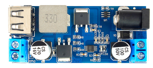
 Design with STEP DOWN XY 3606 in Cirkit Designer
Introduction
The STEP DOWN XY 3606 is a highly efficient step-down voltage regulator designed to convert a higher input voltage into a stable, lower output voltage. This component is widely used in electronic circuits to provide regulated power to devices and modules that require a specific voltage level. Its compact design and adjustable output make it suitable for a variety of applications, including battery-powered devices, microcontroller-based projects, and embedded systems.
Explore Projects Built with STEP DOWN XY 3606
 Open Project in Cirkit Designer
 Open Project in Cirkit Designer
 Open Project in Cirkit Designer
 Open Project in Cirkit Designer
Explore Projects Built with STEP DOWN XY 3606
Open Project in Cirkit DesignerOpen Project in Cirkit DesignerOpen Project in Cirkit DesignerOpen Project in Cirkit DesignerCommon Applications
- Powering microcontrollers (e.g., Arduino, Raspberry Pi)
- Battery charging circuits
- LED drivers
- Robotics and automation systems
- General-purpose DC-DC voltage regulation
Technical Specifications
The STEP DOWN XY 3606 is a versatile and robust component with the following key specifications:
| Parameter | Value |
|---|---|
| Input Voltage Range | 4.0V to 40.0V |
| Output Voltage Range | 1.25V to 36.0V (adjustable via potentiometer) |
| Maximum Output Current | 5A (with proper heat dissipation) |
| Efficiency | Up to 96% |
| Switching Frequency | 150 kHz |
| Operating Temperature | -40°C to +85°C |
| Dimensions | 43mm x 21mm x 14mm |
Pin Configuration and Descriptions
The STEP DOWN XY 3606 module has the following pin configuration:
| Pin Name | Description |
|---|---|
| VIN | Input voltage pin (connect to the higher voltage source) |
| VOUT | Output voltage pin (connect to the load) |
| GND | Ground pin (common ground for input and output) |
Usage Instructions
How to Use the STEP DOWN XY 3606 in a Circuit
Connect the Input Voltage (VIN):
- Attach the positive terminal of your power source to the VIN pin.
- Connect the negative terminal of your power source to the GND pin.
Adjust the Output Voltage:
- Use the onboard potentiometer to set the desired output voltage.
- Turn the potentiometer clockwise to increase the output voltage or counterclockwise to decrease it.
- Use a multimeter to measure the output voltage at the VOUT pin while adjusting.
Connect the Load:
- Attach the positive terminal of your load to the VOUT pin.
- Connect the negative terminal of your load to the GND pin.
Ensure Proper Heat Dissipation:
- If the output current exceeds 2A, attach a heatsink to the module to prevent overheating.
Important Considerations and Best Practices
- Input Voltage: Ensure the input voltage is at least 1.5V higher than the desired output voltage for proper regulation.
- Current Limitation: Do not exceed the maximum output current of 5A. Use a heatsink for high-current applications.
- Polarity Protection: Double-check the polarity of the input and output connections to avoid damage to the module.
- Noise Filtering: Add capacitors (e.g., 100µF electrolytic and 0.1µF ceramic) at the input and output for improved stability and reduced noise.
Example: Using the STEP DOWN XY 3606 with an Arduino UNO
The STEP DOWN XY 3606 can be used to power an Arduino UNO by stepping down a 12V input to 5V. Below is an example circuit and Arduino code:
Circuit Connections
- Connect a 12V DC power source to the VIN and GND pins of the XY 3606.
- Adjust the output voltage to 5V using the potentiometer.
- Connect the VOUT pin to the 5V pin of the Arduino UNO.
- Connect the GND pin of the XY 3606 to the GND pin of the Arduino UNO.
Arduino Code Example
// Example code to blink an LED connected to pin 13 of the Arduino UNO
// Ensure the Arduino is powered via the STEP DOWN XY 3606 module

void setup() {
  pinMode(13, OUTPUT); // Set pin 13 as an output pin
}

void loop() {
  digitalWrite(13, HIGH); // Turn the LED on
  delay(1000);            // Wait for 1 second
  digitalWrite(13, LOW);  // Turn the LED off
  delay(1000);            // Wait for 1 second
}
Troubleshooting and FAQs
Common Issues and Solutions
No Output Voltage:
- Cause: Incorrect input connections or insufficient input voltage.
- Solution: Verify the polarity of the input connections and ensure the input voltage is within the specified range.
Output Voltage Not Adjustable:
- Cause: Faulty potentiometer or incorrect adjustment.
- Solution: Check the potentiometer for damage and adjust it slowly while monitoring the output voltage.
Overheating:
- Cause: High output current or insufficient heat dissipation.
- Solution: Attach a heatsink to the module and ensure proper ventilation.
Load Not Powering On:
- Cause: Output voltage too low or load requires more current than the module can provide.
- Solution: Verify the output voltage and ensure the load's current requirements are within the module's limits.
FAQs
Q: Can the STEP DOWN XY 3606 be used with a battery as the input source?
A: Yes, the module can be powered by a battery as long as the battery voltage is within the input voltage range (4.0V to 40.0V).
Q: Is the module protected against reverse polarity?
A: No, the module does not have built-in reverse polarity protection. Ensure correct polarity to avoid damage.
Q: Can I use the module to power multiple devices simultaneously?
A: Yes, as long as the total current draw of all devices does not exceed the maximum output current of 5A.
Q: How do I know if the module is overheating?
A: If the module becomes too hot to touch or the output voltage becomes unstable, it may be overheating. Use a heatsink to mitigate this issue.