Cirkit Designer Logo
Cirkit Designer
Your all-in-one circuit design IDE
Home / 
Component Documentation

How to Use Motor Driver: Examples, Pinouts, and Specs

Image of Motor Driver
Cirkit Designer LogoDesign with Motor Driver in Cirkit Designer

Introduction

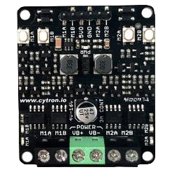
The Maker MDD3A Motor Driver is a versatile and powerful electronic device designed to control and drive the motion of motors. It is capable of handling high current and voltage, making it suitable for a wide range of applications including robotics, industrial automation, and hobbyist projects. The MDD3A allows for precise control over the speed and direction of DC motors, stepper motors, and servo motors.

Explore Projects Built with Motor Driver

Use Cirkit Designer to design, explore, and prototype these projects online. Some projects support real-time simulation. Click "Open Project" to start designing instantly!
ESP32 and L298N Motor Driver Controlled Battery-Powered Robotic Car
Image of ESP 32 BT BOT: A project utilizing Motor Driver in a practical application
This circuit is a motor control system powered by a 12V battery, utilizing an L298N motor driver to control four DC gearmotors. An ESP32 microcontroller is used to send control signals to the motor driver, enabling precise control of the motors for applications such as a robotic vehicle.
Cirkit Designer LogoOpen Project in Cirkit Designer
ESP32-Controlled Dual Motor Driver for Robotic Vehicle
Image of ESP 32 BT BOT: A project utilizing Motor Driver in a practical application
This circuit is designed to control four DC gearmotors using an L298N motor driver module, which is interfaced with an ESP32 microcontroller. The ESP32 uses its GPIO pins to send control signals to the L298N driver, enabling the independent operation of the motors, such as direction and speed control. Power is supplied by a 12V battery connected to the motor driver, with the ESP32 receiving its power through a voltage regulator on the L298N module.
Cirkit Designer LogoOpen Project in Cirkit Designer
ESP32 and L298N Motor Driver-Based Wi-Fi Controlled Robotic Car
Image of ESP 32 BT BOT: A project utilizing Motor Driver in a practical application
This circuit is a motor control system using an ESP32 microcontroller and an L298N motor driver to control four DC gear motors. The ESP32 provides control signals to the L298N, which in turn drives the motors, powered by a 12V battery, enabling bidirectional control of the motors for applications such as a robotic vehicle.
Cirkit Designer LogoOpen Project in Cirkit Designer
DC Motor Control System with BTS7960 Motor Driver and Arcade Buttons
Image of Hanif: A project utilizing Motor Driver in a practical application
This circuit controls a DC motor using a BTS7960 motor driver, powered by a 12V power supply and regulated by a DC-DC step-down converter. The motor's operation is controlled via two arcade buttons and a rocker switch, allowing for user input to manage the motor's direction and power.
Cirkit Designer LogoOpen Project in Cirkit Designer

Explore Projects Built with Motor Driver

Use Cirkit Designer to design, explore, and prototype these projects online. Some projects support real-time simulation. Click "Open Project" to start designing instantly!
Image of ESP 32 BT BOT: A project utilizing Motor Driver in a practical application
ESP32 and L298N Motor Driver Controlled Battery-Powered Robotic Car
This circuit is a motor control system powered by a 12V battery, utilizing an L298N motor driver to control four DC gearmotors. An ESP32 microcontroller is used to send control signals to the motor driver, enabling precise control of the motors for applications such as a robotic vehicle.
Cirkit Designer LogoOpen Project in Cirkit Designer
Image of ESP 32 BT BOT: A project utilizing Motor Driver in a practical application
ESP32-Controlled Dual Motor Driver for Robotic Vehicle
This circuit is designed to control four DC gearmotors using an L298N motor driver module, which is interfaced with an ESP32 microcontroller. The ESP32 uses its GPIO pins to send control signals to the L298N driver, enabling the independent operation of the motors, such as direction and speed control. Power is supplied by a 12V battery connected to the motor driver, with the ESP32 receiving its power through a voltage regulator on the L298N module.
Cirkit Designer LogoOpen Project in Cirkit Designer
Image of ESP 32 BT BOT: A project utilizing Motor Driver in a practical application
ESP32 and L298N Motor Driver-Based Wi-Fi Controlled Robotic Car
This circuit is a motor control system using an ESP32 microcontroller and an L298N motor driver to control four DC gear motors. The ESP32 provides control signals to the L298N, which in turn drives the motors, powered by a 12V battery, enabling bidirectional control of the motors for applications such as a robotic vehicle.
Cirkit Designer LogoOpen Project in Cirkit Designer
Image of Hanif: A project utilizing Motor Driver in a practical application
DC Motor Control System with BTS7960 Motor Driver and Arcade Buttons
This circuit controls a DC motor using a BTS7960 motor driver, powered by a 12V power supply and regulated by a DC-DC step-down converter. The motor's operation is controlled via two arcade buttons and a rocker switch, allowing for user input to manage the motor's direction and power.
Cirkit Designer LogoOpen Project in Cirkit Designer

Common Applications and Use Cases

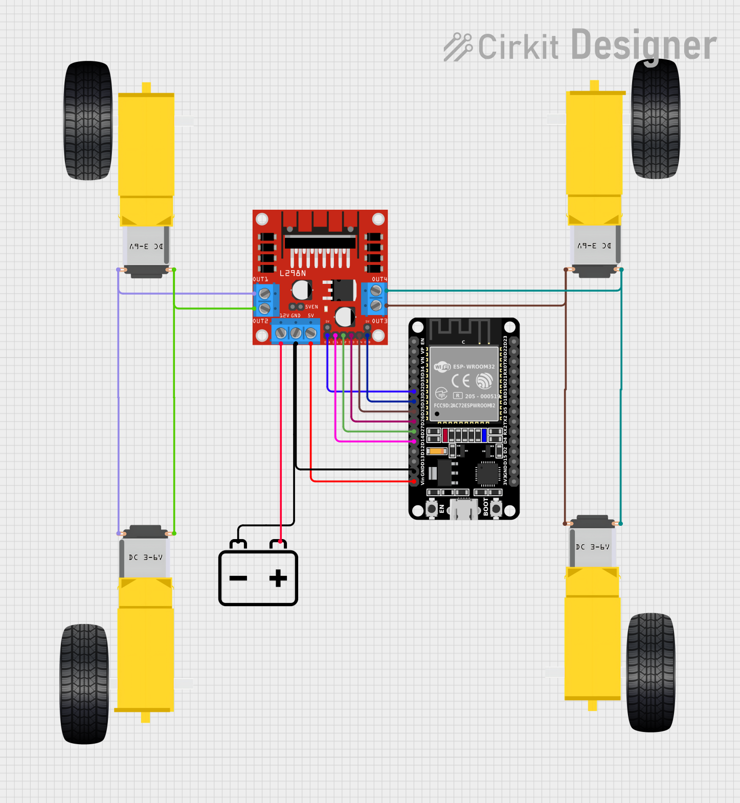
  • Robotics: Driving wheels or actuator motors.
  • CNC machines: Controlling stepper motors for precise movements.
  • Electric vehicles: Managing propulsion and steering motors.
  • Hobby projects: Controlling motors in RC cars, drones, and more.

Technical Specifications

Key Technical Details

  • Operating Voltage: 5V to 30V
  • Continuous Current: Up to 3A per channel
  • Peak Current: Up to 6A per channel (short duration)
  • Control Signal Input Voltage: 3.3V to 5V (TTL compatible)
  • Control Modes: Direction/Speed (PWM), Forward/Reverse, Brake

Pin Configuration and Descriptions

Pin Number Pin Name Description
1 VM Motor power supply (5V-30V)
2 GND Ground connection
3 VCC Logic power supply (5V)
4 AIN1 Input control A1
5 AIN2 Input control A2
6 PWMA PWM input for speed control of motor A
7 STBY Standby mode (active low)
8 BIN1 Input control B1
9 BIN2 Input control B2
10 PWMB PWM input for speed control of motor B
11 AOUT1 Motor A output 1
12 AOUT2 Motor A output 2
13 BOUT1 Motor B output 1
14 BOUT2 Motor B output 2

Usage Instructions

How to Use the MDD3A in a Circuit

  1. Power Connections:

    • Connect the motor power supply to the VM and GND pins.
    • Connect the logic power supply to the VCC and GND pins.
  2. Motor Connections:

    • Connect your motor to the AOUT1 and AOUT2 pins for motor A, or BOUT1 and BOUT2 for motor B.
  3. Control Signal Connections:

    • Connect your control signals (e.g., from an Arduino) to the AIN1, AIN2, PWMA, BIN1, BIN2, and PWMB pins as required.
  4. Enable the Driver:

    • Set the STBY pin to high to enable the driver.

Important Considerations and Best Practices

  • Ensure that the power supply voltage and current do not exceed the specifications.
  • Use appropriate heat sinks if operating near the maximum current rating.
  • Always provide a common ground between the logic source (e.g., Arduino) and the motor driver.
  • Use PWM signals for speed control and digital signals to set the direction.

Example Code for Arduino UNO

// Define motor driver pins
#define AIN1 2
#define AIN2 3
#define PWMA 5 // PWM pin for speed control

void setup() {
  // Set motor driver pins as outputs
  pinMode(AIN1, OUTPUT);
  pinMode(AIN2, OUTPUT);
  pinMode(PWMA, OUTPUT);
}

void loop() {
  // Set motor A direction to forward
  digitalWrite(AIN1, HIGH);
  digitalWrite(AIN2, LOW);
  
  // Set motor A speed to 50%
  analogWrite(PWMA, 127); // PWM value between 0 (0%) and 255 (100%)
  
  delay(2000); // Run motor for 2 seconds
  
  // Stop motor A
  digitalWrite(AIN1, LOW);
  digitalWrite(AIN2, LOW);
  
  delay(1000); // Wait for 1 second
}

Troubleshooting and FAQs

Common Issues

  • Motor not running: Check power supply connections, ensure STBY pin is high, and verify control signals.
  • Motor running hot: Reduce the load or current, check for proper ventilation and heat sinking.
  • Inconsistent motor speed: Ensure PWM signal is stable and within the correct voltage range.

Solutions and Tips for Troubleshooting

  • Double-check wiring and connections for any loose or incorrect connections.
  • Use a multimeter to verify the voltage levels at the power supply and control pins.
  • If using PWM for speed control, ensure the frequency is within the acceptable range for the motor driver.

FAQs

Q: Can I control two motors independently with the MDD3A? A: Yes, the MDD3A has two channels, allowing for independent control of two motors.

Q: What is the maximum frequency for the PWM signal? A: The MDD3A can typically handle PWM frequencies up to 25kHz. Check the datasheet for exact specifications.

Q: Can I use the MDD3A with a microcontroller operating at 3.3V logic? A: Yes, the control signal input voltage is compatible with 3.3V logic levels.

For further assistance, please refer to the Maker MDD3A datasheet or contact technical support.