How to Use 12V UPS Board: Examples, Pinouts, and Specs
Introduction
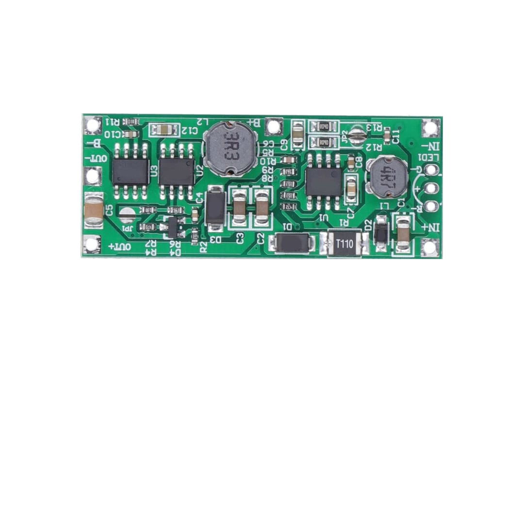
A 12V Uninterruptible Power Supply (UPS) board is a compact and efficient solution for providing backup power to electronic devices during power outages. It ensures continuous operation by seamlessly switching between mains power and a connected battery. These boards are commonly used in applications where uninterrupted power is critical, such as routers, modems, IoT devices, security systems, and small embedded systems.
Explore Projects Built with 12V UPS Board

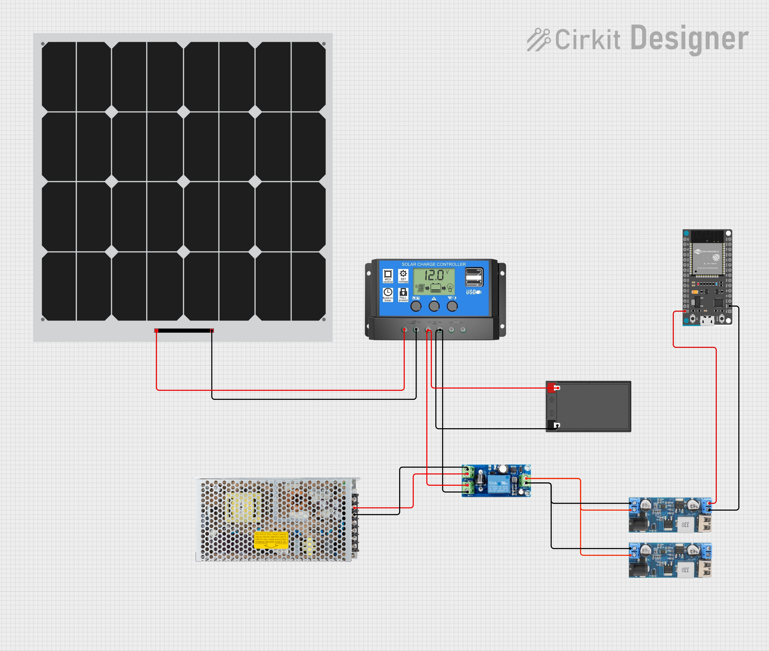
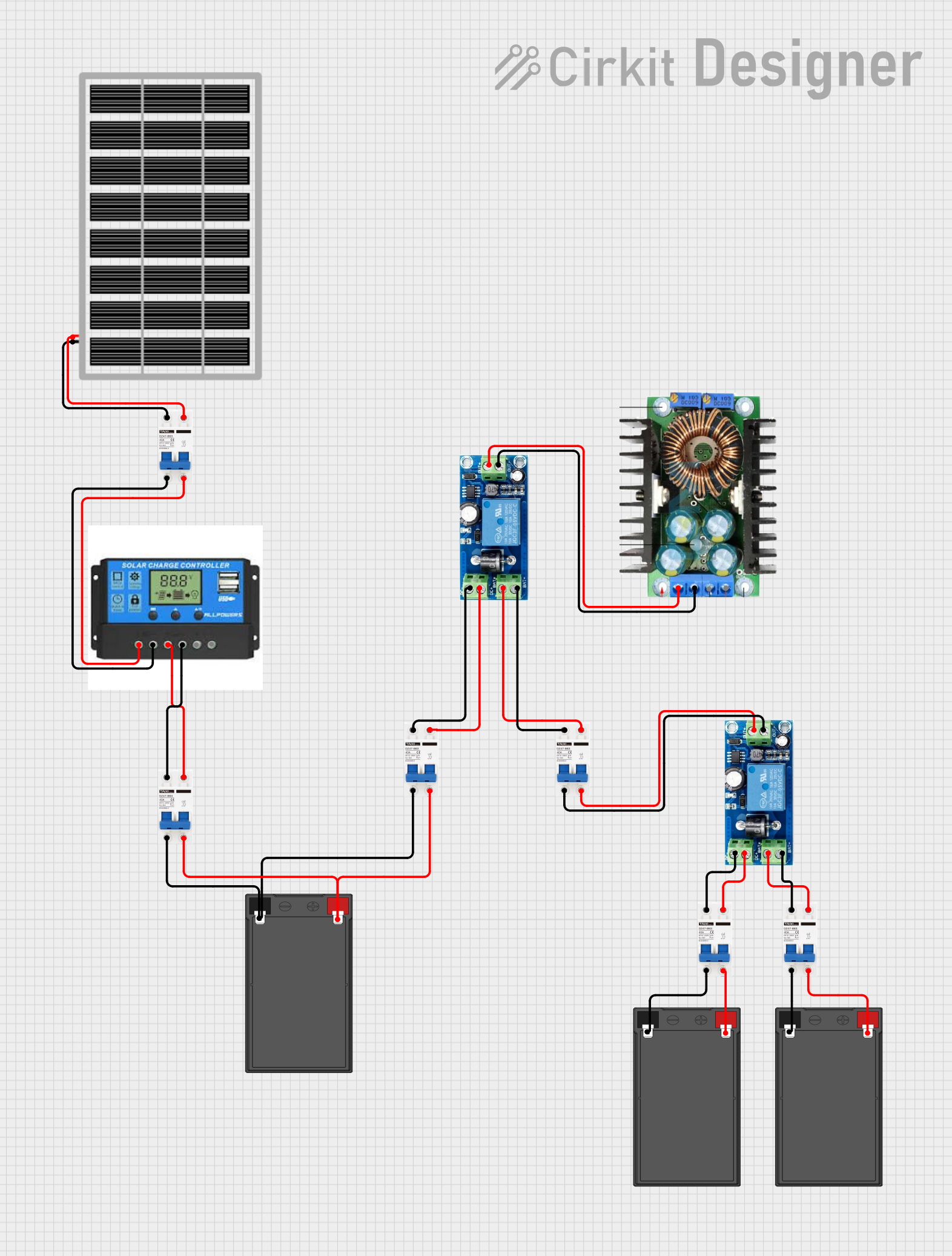

Explore Projects Built with 12V UPS Board
Common Applications and Use Cases
- Powering routers and modems during power outages to maintain internet connectivity.
- Providing backup power to IoT devices and smart home systems.
- Ensuring uninterrupted operation of security cameras and alarm systems.
- Supporting embedded systems and microcontrollers in critical applications.
- Backup power for small medical devices or monitoring systems.
Technical Specifications
Below are the key technical details of a typical 12V UPS board:
| Parameter | Specification |
|---|---|
| Input Voltage Range | 12V DC ± 10% |
| Output Voltage | 12V DC ± 5% |
| Maximum Output Current | 2A to 5A (varies by model) |
| Battery Type Supported | 12V Lead-Acid or Lithium-Ion |
| Battery Capacity Range | 1.2Ah to 7Ah (recommended) |
| Charging Current | 500mA to 1A (adjustable on some models) |
| Efficiency | ≥ 85% |
| Switching Time | < 10ms |
| Protection Features | Overcharge, Overdischarge, Short Circuit, Overcurrent |
| Operating Temperature | -10°C to 50°C |
Pin Configuration and Descriptions
The 12V UPS board typically has the following connectors and pins:
| Pin/Connector | Description |
|---|---|
| VIN | Input for 12V DC power supply (mains power). |
| VOUT | Output for 12V DC to power the connected load. |
| BAT+ | Positive terminal for the external 12V battery. |
| BAT- | Negative terminal for the external 12V battery. |
| CHG LED | LED indicator for charging status (ON when charging). |
| PWR LED | LED indicator for power status (ON when output is active). |
| GND | Ground connection for the circuit. |
Usage Instructions
How to Use the 12V UPS Board in a Circuit
Connect the Battery:
- Attach the positive terminal of the 12V battery to the
BAT+pin and the negative terminal to theBAT-pin. - Ensure the battery is fully charged before first use for optimal performance.
- Attach the positive terminal of the 12V battery to the
Connect the Input Power Supply:
- Connect a 12V DC power adapter to the
VINpin. This will act as the primary power source.
- Connect a 12V DC power adapter to the
Connect the Load:
- Attach the device you want to power (e.g., router, IoT device) to the
VOUTpin.
- Attach the device you want to power (e.g., router, IoT device) to the
Power On:
- Turn on the input power supply. The board will automatically charge the battery and supply power to the load.
Automatic Switching:
- During a power outage, the board will automatically switch to battery power within 10ms, ensuring uninterrupted operation.
Important Considerations and Best Practices
- Battery Selection: Use a compatible 12V battery with the recommended capacity (1.2Ah to 7Ah). Ensure the battery is in good condition to avoid performance issues.
- Heat Dissipation: Place the board in a well-ventilated area to prevent overheating, especially under high load conditions.
- Load Current: Ensure the connected load does not exceed the maximum output current rating of the board.
- Polarity: Double-check all connections for correct polarity to avoid damage to the board or connected devices.
- Regular Maintenance: Periodically check the battery's health and replace it if necessary to maintain reliable backup power.
Example: Using the 12V UPS Board with an Arduino UNO
The 12V UPS board can be used to power an Arduino UNO during power outages. Below is an example setup:
- Connect the
VOUTpin of the UPS board to the Arduino'sVINpin. - Connect the
GNDpin of the UPS board to the Arduino'sGNDpin. - Ensure the input power supply and battery are properly connected to the UPS board.
Here is a simple Arduino sketch to test the setup:
// Simple Arduino sketch to blink an LED and test UPS functionality
const int ledPin = 13; // Built-in LED pin on Arduino UNO

void setup() {
  pinMode(ledPin, OUTPUT); // Set LED pin as output
}

void loop() {
  digitalWrite(ledPin, HIGH); // Turn LED on
  delay(1000); // Wait for 1 second
  digitalWrite(ledPin, LOW); // Turn LED off
  delay(1000); // Wait for 1 second
}
Disconnect the input power supply to test if the Arduino continues running on battery power.
Troubleshooting and FAQs
Common Issues and Solutions
No Output Power:
- Cause: Battery not connected or discharged.
- Solution: Check the battery connections and ensure the battery is charged.
Battery Not Charging:
- Cause: Faulty input power supply or damaged charging circuit.
- Solution: Verify the input power supply voltage and current. Inspect the board for damage.
Frequent Switching Between Mains and Battery:
- Cause: Unstable input power supply.
- Solution: Use a stable 12V DC adapter with sufficient current capacity.
Overheating:
- Cause: High load or poor ventilation.
- Solution: Reduce the load or improve airflow around the board.
FAQs
Q1: Can I use a 12V Lithium-Ion battery with this board?
A1: Yes, most 12V UPS boards support both lead-acid and lithium-ion batteries. Check the board's specifications to confirm compatibility.
Q2: What happens if the battery is over-discharged?
A2: The board includes over-discharge protection to prevent damage to the battery. However, it is recommended to recharge the battery promptly.
Q3: Can I use this board with a 5V device?
A3: No, the board outputs 12V DC. You will need a step-down converter to use it with 5V devices.
Q4: How long will the battery last during a power outage?
A4: The backup duration depends on the battery capacity and the load current. For example, a 12V 7Ah battery powering a 1A load will last approximately 7 hours.
By following this documentation, you can effectively use the 12V UPS board to ensure uninterrupted power for your electronic devices.