How to Use Photoresistor (LDR) Sensor: Examples, Pinouts, and Specs
Introduction
A photoresistor, or light-dependent resistor (LDR), is a passive electronic component that changes its resistance based on the amount of light it is exposed to. When light intensity increases, the resistance of the LDR decreases, and when light intensity decreases, its resistance increases. This property makes it an ideal component for light-sensing applications.
Explore Projects Built with Photoresistor (LDR) Sensor
Explore Projects Built with Photoresistor (LDR) Sensor
Common Applications and Use Cases
- Automatic lighting systems (e.g., streetlights that turn on at night)
- Light meters and brightness detection
- Solar tracking systems
- Alarm systems triggered by changes in light
- DIY electronics projects involving light sensing
Technical Specifications
Below are the general technical specifications for a typical photoresistor (LDR). Note that exact values may vary depending on the specific model.
| Parameter | Value |
|---|---|
| Resistance in Darkness | 1 MΩ to 10 MΩ |
| Resistance in Bright Light | 1 kΩ to 10 kΩ |
| Maximum Voltage | 150 V |
| Maximum Power Dissipation | 100 mW |
| Response Time | Rise: 20 ms, Fall: 30 ms |
| Operating Temperature | -30°C to +70°C |
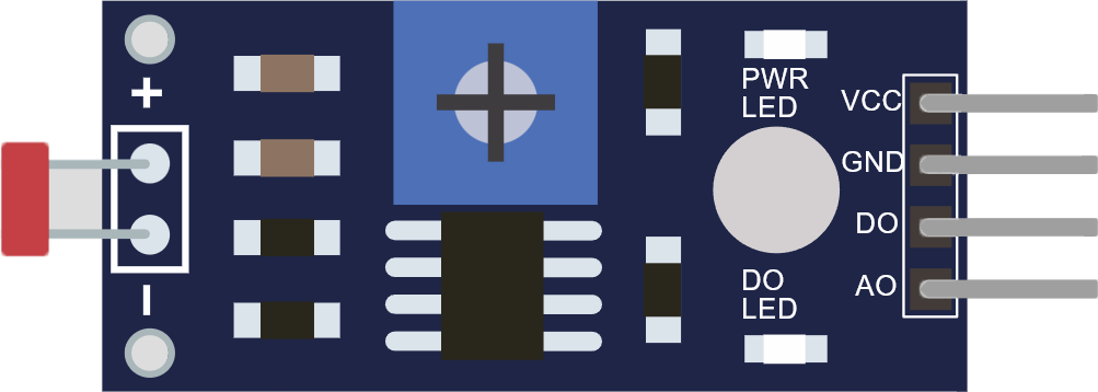
Pin Configuration and Descriptions
A photoresistor does not have a specific pin configuration as it is a two-terminal device. The two terminals are interchangeable and can be connected in either orientation. Below is a table summarizing the terminals:
| Pin | Description |
|---|---|
| Pin 1 | Connects to one side of the circuit |
| Pin 2 | Connects to the other side of the circuit |
Usage Instructions
How to Use the Component in a Circuit
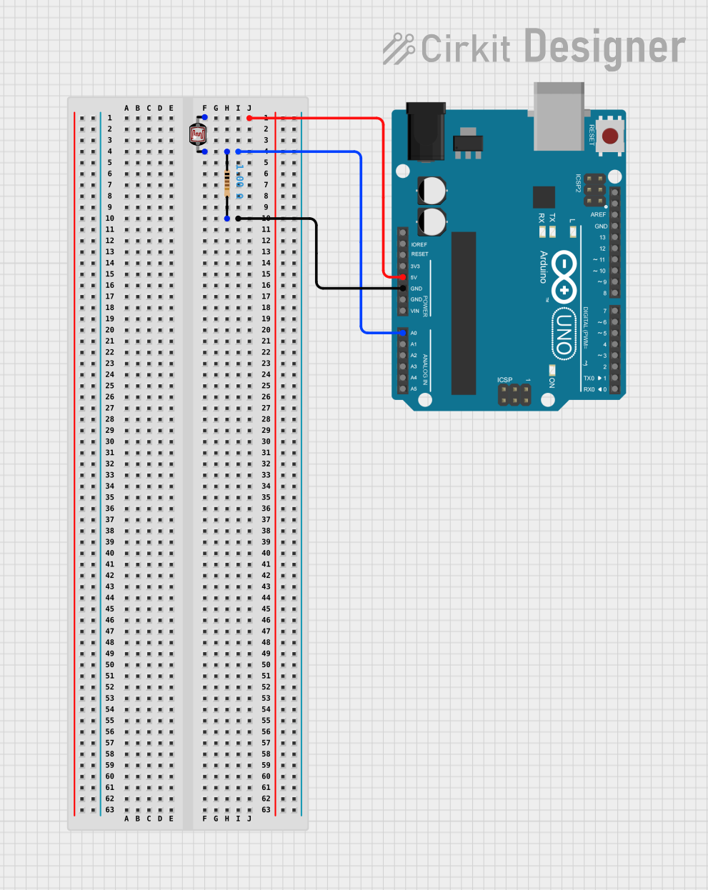
Basic Circuit Setup:
- Connect one terminal of the LDR to a voltage source (e.g., 5V).
- Connect the other terminal to a resistor (commonly 10 kΩ) in series.
- Connect the free end of the resistor to ground.
- The junction between the LDR and the resistor serves as the output, where the voltage varies based on light intensity.
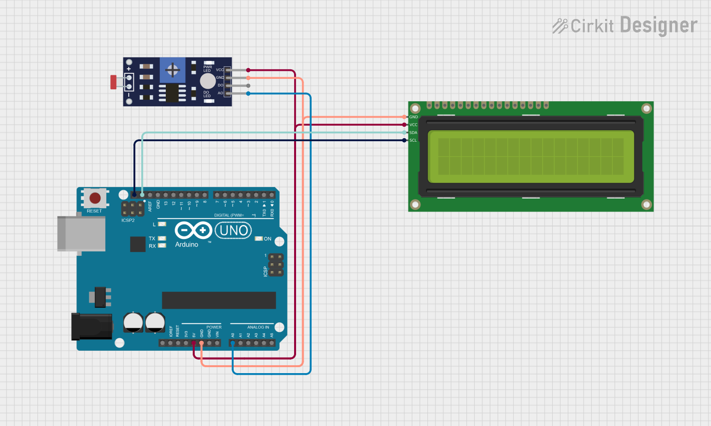
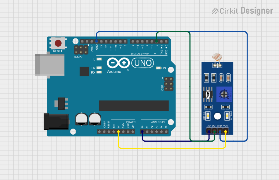
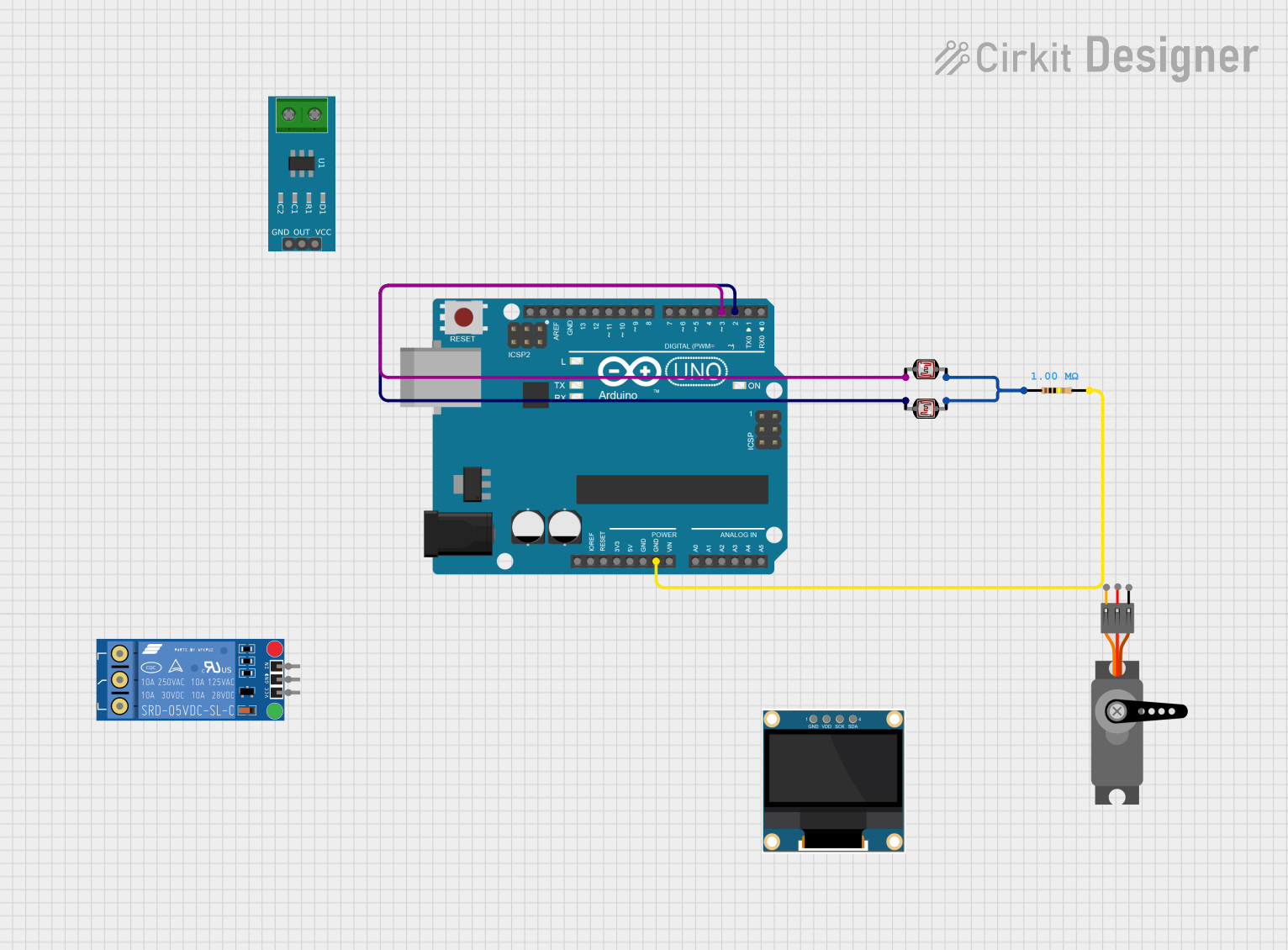
Interfacing with an Arduino UNO:
- Connect the LDR-resistor junction to an analog input pin (e.g., A0) on the Arduino.
- Use the Arduino's ADC (Analog-to-Digital Converter) to read the voltage and determine light intensity.
Important Considerations and Best Practices
- Resistor Selection: Choose a resistor value that matches the expected light conditions. For general use, a 10 kΩ resistor is common.
- Ambient Light: Ensure the LDR is not exposed to unwanted light sources that could interfere with its operation.
- Response Time: LDRs have a slower response time compared to photodiodes or phototransistors, so they may not be suitable for high-speed light detection.
- Voltage Divider: Always use the LDR in a voltage divider configuration to convert resistance changes into measurable voltage changes.
Example Code for Arduino UNO
Below is an example of how to use a photoresistor with an Arduino UNO to measure light intensity:
// Define the analog pin connected to the LDR
const int ldrPin = A0;

void setup() {
  // Initialize serial communication for debugging
  Serial.begin(9600);
}

void loop() {
  // Read the analog value from the LDR
  int ldrValue = analogRead(ldrPin);

  // Convert the analog value to a voltage (assuming 5V reference)
  float voltage = ldrValue * (5.0 / 1023.0);

  // Print the LDR value and voltage to the Serial Monitor
  Serial.print("LDR Value: ");
  Serial.print(ldrValue);
  Serial.print(" | Voltage: ");
  Serial.println(voltage);

  // Add a small delay to avoid flooding the Serial Monitor
  delay(500);
}
Troubleshooting and FAQs
Common Issues and Solutions
No Change in Output Voltage:
- Cause: Incorrect wiring or damaged LDR.
- Solution: Double-check the circuit connections and ensure the LDR is functional.
Inconsistent Readings:
- Cause: Electrical noise or unstable light source.
- Solution: Use a capacitor (e.g., 0.1 µF) across the LDR terminals to filter noise.
Output Voltage Always High or Low:
- Cause: Incorrect resistor value in the voltage divider.
- Solution: Adjust the resistor value to better match the light conditions.
Slow Response to Light Changes:
- Cause: LDR's inherent response time.
- Solution: Consider using a photodiode or phototransistor for faster response.
FAQs
Q1: Can I use an LDR to measure precise light intensity?
A1: LDRs are not highly accurate for precise measurements. For precise light intensity measurements, consider using a calibrated light sensor like a photodiode or a lux sensor.
Q2: Can I use an LDR in outdoor applications?
A2: Yes, but ensure the LDR is protected from environmental factors like moisture and extreme temperatures.
Q3: What happens if I reverse the LDR terminals?
A3: Nothing, as the LDR is not polarized. The terminals are interchangeable.
Q4: Can I use an LDR with a 3.3V system?
A4: Yes, the LDR works with both 3.3V and 5V systems. Adjust the resistor value in the voltage divider accordingly.