
How to Use Slide Potentiometer: Examples, Pinouts, and Specs

 Design with Slide Potentiometer in Cirkit Designer
Introduction
A slide potentiometer is a type of variable resistor that allows users to adjust resistance by sliding a contact along a resistive element. This component is widely used in applications requiring adjustable levels, such as audio volume control, lighting dimmers, and other user interface controls. Its linear motion makes it intuitive for precise adjustments, making it a popular choice in both consumer electronics and industrial equipment.
Explore Projects Built with Slide Potentiometer
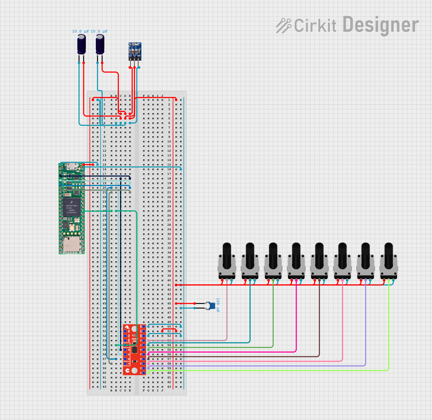 Open Project in Cirkit Designer
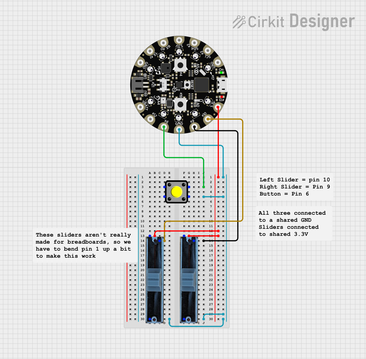 Open Project in Cirkit Designer
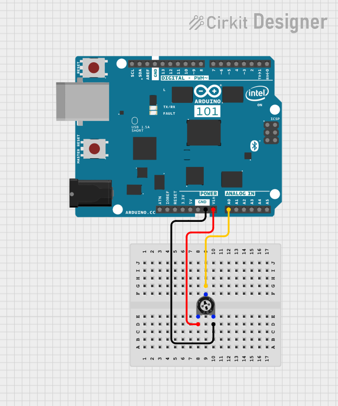 Open Project in Cirkit Designer
 Open Project in Cirkit Designer
Explore Projects Built with Slide Potentiometer
Open Project in Cirkit DesignerOpen Project in Cirkit DesignerOpen Project in Cirkit DesignerOpen Project in Cirkit DesignerTechnical Specifications
- Type: Linear or logarithmic slide potentiometer
- Resistance Range: Typically 1 kΩ to 100 kΩ (varies by model)
- Power Rating: 0.1 W to 0.5 W (depending on the model)
- Travel Length: Commonly 30 mm, 45 mm, or 60 mm
- Tolerance: ±10% to ±20%
- Operating Voltage: Up to 50 V DC
- Operating Temperature: -10°C to +70°C
- Lifespan: Typically 10,000 to 100,000 cycles
Pin Configuration and Descriptions
The slide potentiometer typically has three pins:
| Pin Number | Name | Description |
|---|---|---|
| 1 | VCC/Input | Connects to the positive voltage supply or input signal. |
| 2 | Wiper/Output | The adjustable output voltage or signal, determined by the slider position. |
| 3 | GND | Connects to ground or the negative terminal of the circuit. |
Usage Instructions
How to Use the Slide Potentiometer in a Circuit
Connect the Pins:
- Pin 1 (VCC/Input): Connect to the positive voltage supply (e.g., 5V or 3.3V).
- Pin 3 (GND): Connect to the ground of the circuit.
- Pin 2 (Wiper/Output): Connect to the input of the device or circuit where the adjustable signal is needed.
Adjust the Slider:
- Move the slider along the resistive track to change the resistance and adjust the output voltage at the wiper pin.
Voltage Divider Configuration:
- The slide potentiometer acts as a voltage divider. The output voltage at the wiper pin is proportional to the slider's position: [ V_{out} = V_{in} \times \frac{R_2}{R_1 + R_2} ] where ( R_1 ) and ( R_2 ) are the resistances on either side of the wiper.
Important Considerations and Best Practices
- Power Rating: Ensure the potentiometer's power rating is not exceeded to avoid damage.
- Mechanical Stress: Avoid applying excessive force to the slider to prevent wear or breakage.
- Debouncing: When used in digital circuits, consider implementing software debouncing to handle noise caused by slider movement.
- Mounting: Secure the potentiometer properly to prevent movement during operation.
Example: Using a Slide Potentiometer with Arduino UNO
The following example demonstrates how to read the position of a slide potentiometer using an Arduino UNO and display the value on the Serial Monitor.
// Define the analog pin connected to the potentiometer's wiper (Pin 2)
const int potPin = A0;

void setup() {
  Serial.begin(9600); // Initialize serial communication at 9600 baud
}

void loop() {
  int potValue = analogRead(potPin); // Read the analog value (0-1023)

  // Map the potentiometer value to a percentage (0-100%)
  float percentage = (potValue / 1023.0) * 100;

  // Print the raw value and percentage to the Serial Monitor
  Serial.print("Raw Value: ");
  Serial.print(potValue);
  Serial.print(" | Percentage: ");
  Serial.print(percentage);
  Serial.println("%");

  delay(100); // Add a small delay for stability
}
Troubleshooting and FAQs
Common Issues
No Output Signal:
- Cause: Incorrect wiring or loose connections.
- Solution: Verify that all pins are connected correctly and securely.
Inconsistent or Noisy Output:
- Cause: Dust or debris on the resistive track.
- Solution: Clean the potentiometer with compressed air or contact cleaner.
Slider Stuck or Difficult to Move:
- Cause: Mechanical wear or damage.
- Solution: Inspect for physical damage and replace the potentiometer if necessary.
Output Voltage Does Not Change:
- Cause: Faulty potentiometer or incorrect circuit configuration.
- Solution: Test the potentiometer with a multimeter to ensure it is functioning properly.
FAQs
Q1: Can I use a slide potentiometer for digital input?
A1: Yes, but you will need to connect it to an analog-to-digital converter (ADC) to interpret the analog signal as a digital value.
Q2: What is the difference between linear and logarithmic potentiometers?
A2: A linear potentiometer provides a proportional change in resistance with slider movement, while a logarithmic potentiometer changes resistance exponentially, often used in audio applications.
Q3: How do I choose the correct resistance value for my application?
A3: Select a resistance value that matches the input impedance of your circuit and provides the desired range of adjustment.
Q4: Can I use a slide potentiometer to control motor speed?
A4: Yes, but it is typically used to control the input signal of a motor driver or PWM circuit, not directly connected to the motor.