How to Use Relay : Examples, Pinouts, and Specs
Introduction
A relay is an electrically operated switch that uses an electromagnet to mechanically operate a switch. This allows a low power signal to control a higher power circuit. Relays are commonly used in various applications, including:
- Automotive systems: Controlling headlights, horns, and other high-power devices.
- Home automation: Switching lights, fans, and other household appliances.
- Industrial automation: Controlling motors, solenoids, and other heavy machinery.
- Microcontroller projects: Interfacing with Arduino, Raspberry Pi, and other development boards to control high-power devices.
Explore Projects Built with Relay

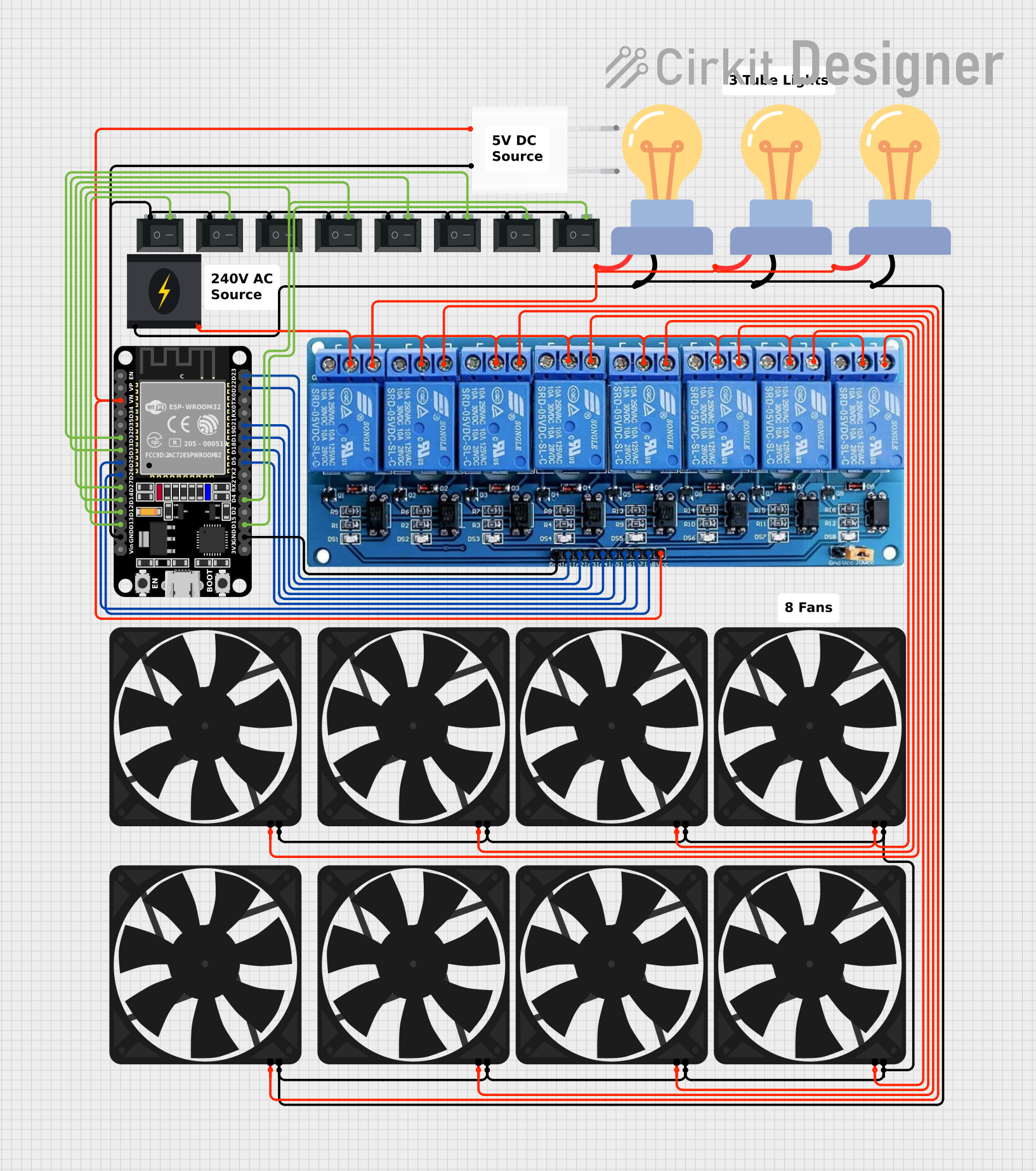


Explore Projects Built with Relay
Technical Specifications
Key Technical Details
| Parameter | Value |
|---|---|
| Coil Voltage | 5V, 12V, 24V |
| Coil Current | 70mA (5V), 30mA (12V), 20mA (24V) |
| Contact Rating | 10A @ 250VAC, 10A @ 30VDC |
| Contact Resistance | < 100mΩ |
| Operate Time | 10ms |
| Release Time | 5ms |
| Insulation Resistance | > 100MΩ @ 500VDC |
| Dielectric Strength | 500VAC (coil to contact) |
| Mechanical Life | 10^7 operations |
| Electrical Life | 10^5 operations |
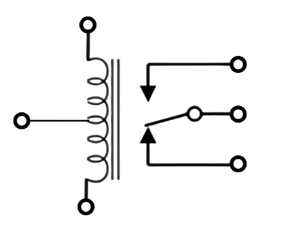
Pin Configuration and Descriptions
| Pin Number | Name | Description |
|---|---|---|
| 1 | Coil+ | Positive terminal of the relay coil |
| 2 | Coil- | Negative terminal of the relay coil |
| 3 | COM | Common terminal of the relay switch |
| 4 | NC (Normally Closed) | Connected to COM when relay is inactive |
| 5 | NO (Normally Open) | Connected to COM when relay is active |
Usage Instructions
How to Use the Relay in a Circuit
- Power the Coil: Connect the coil terminals (Pin 1 and Pin 2) to a suitable power source. For example, if you are using a 5V relay, connect Pin 1 to 5V and Pin 2 to ground.
- Control the Relay: Use a low-power control signal (e.g., from a microcontroller) to energize the coil. This will cause the relay to switch from its default state (NC connected to COM) to its active state (NO connected to COM).
- Connect the Load: Connect the high-power circuit to the COM and NO or NC terminals, depending on whether you want the circuit to be normally open or normally closed.
Important Considerations and Best Practices
- Flyback Diode: Always use a flyback diode across the relay coil to protect the driving circuit from voltage spikes generated when the relay is turned off.
- Current Rating: Ensure that the relay's contact rating is suitable for the load you are switching.
- Isolation: Use optocouplers or other isolation techniques if the control circuit and the load circuit operate at different voltage levels.
- Heat Dissipation: Ensure adequate ventilation or heat sinking if the relay is switching high currents frequently.
Example Circuit with Arduino UNO
/*
 * Example code to control a relay with an Arduino UNO.
 * The relay is connected to digital pin 7.
 */

const int relayPin = 7; // Pin connected to the relay

void setup() {
  pinMode(relayPin, OUTPUT); // Set the relay pin as an output
}

void loop() {
  digitalWrite(relayPin, HIGH); // Turn the relay on
  delay(1000); // Wait for 1 second
  digitalWrite(relayPin, LOW); // Turn the relay off
  delay(1000); // Wait for 1 second
}
Troubleshooting and FAQs
Common Issues and Solutions
Relay Not Switching:
- Check Power Supply: Ensure the coil is receiving the correct voltage.
- Control Signal: Verify that the control signal is correctly driving the relay.
- Connections: Double-check all connections for loose or incorrect wiring.
Relay Chattering:
- Power Supply Stability: Ensure the power supply is stable and not fluctuating.
- Flyback Diode: Make sure a flyback diode is installed across the relay coil.
Overheating:
- Current Rating: Ensure the relay is not switching a load that exceeds its current rating.
- Ventilation: Provide adequate ventilation or heat sinking.
FAQs
Q: Can I use a relay to switch AC loads? A: Yes, relays can switch both AC and DC loads. Ensure the relay's contact rating matches the load requirements.
Q: How do I know if my relay is working? A: You can hear a clicking sound when the relay switches. Additionally, you can measure the continuity between COM and NO/NC terminals to verify the switching.
Q: Can I control multiple relays with a single Arduino? A: Yes, you can control multiple relays with an Arduino by connecting each relay to a different digital pin and using the appropriate code to control each pin.
This documentation provides a comprehensive guide to understanding, using, and troubleshooting relays in various applications. Whether you are a beginner or an experienced user, this guide will help you effectively integrate relays into your projects.