How to Use JGA25-371dc motor with encoder: Examples, Pinouts, and Specs
Introduction
The JGA25-371 DC motor with encoder is a compact and versatile motor designed for applications requiring precise control of speed and position. This motor integrates an encoder, which provides real-time feedback on the motor's rotational position and speed, making it ideal for robotics, automation systems, and other projects where accuracy and control are critical.
Explore Projects Built with JGA25-371dc motor with encoder


Explore Projects Built with JGA25-371dc motor with encoder
Common Applications
- Robotic arms and mobile robots
- Automated conveyor systems
- Precision control in industrial machinery
- DIY electronics and Arduino-based projects
- Motorized camera sliders and gimbals
Technical Specifications
Below are the key technical details of the JGA25-371 DC motor with encoder:
| Parameter | Value |
|---|---|
| Operating Voltage | 6V to 12V |
| Rated Voltage | 12V |
| No-Load Speed | 100 RPM to 600 RPM (varies by model) |
| Stall Torque | Up to 5 kg·cm |
| Gear Ratio | 1:34 to 1:1000 (varies by model) |
| Encoder Resolution | 11 pulses per revolution (PPR) |
| Motor Shaft Diameter | 4 mm |
| Motor Dimensions | 25 mm (diameter) x 37 mm (length) |
| Current Consumption | 100 mA (no load), up to 1.2 A (stall) |
| Output Shaft Type | D-shaped |
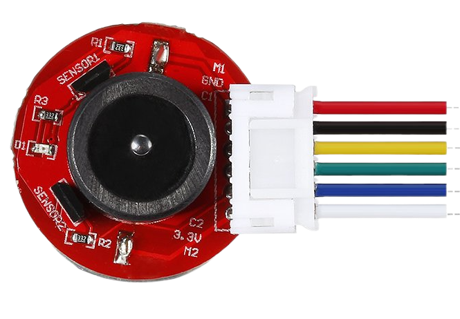
Pin Configuration and Descriptions
The JGA25-371 motor with encoder typically has six wires for connection. Below is the pin configuration:
| Wire Color | Function | Description |
|---|---|---|
| Red | Motor Power (+) | Connect to the positive terminal of the power supply. |
| Black | Motor Power (-) | Connect to the negative terminal of the power supply. |
| Yellow | Encoder A | Outputs pulses for channel A of the encoder. |
| Green | Encoder B | Outputs pulses for channel B of the encoder. |
| Blue | Encoder Power (+) | Connect to a 5V power source for the encoder. |
| White | Encoder Ground (-) | Connect to the ground of the power source. |
Usage Instructions
How to Use the JGA25-371 DC Motor with Encoder in a Circuit
- Power the Motor: Connect the red and black wires to a DC power supply or motor driver. Ensure the voltage matches the motor's rated voltage (e.g., 12V).
- Connect the Encoder:
- Connect the blue wire to a 5V power source.
- Connect the white wire to the ground of the power source.
- Connect the yellow and green wires to the input pins of a microcontroller (e.g., Arduino) to read encoder signals.
- Use a Motor Driver: To control the motor's speed and direction, use an H-bridge motor driver (e.g., L298N or L293D). The motor driver will allow you to interface the motor with a microcontroller safely.
Important Considerations and Best Practices
- Power Supply: Ensure the power supply can provide sufficient current for the motor, especially under load conditions.
- Encoder Signal Handling: Use pull-up resistors on the encoder signal lines (yellow and green) if the microcontroller requires them for stable readings.
- Motor Driver Selection: Choose a motor driver that can handle the motor's stall current to prevent damage.
- Noise Filtering: Add capacitors across the motor terminals to reduce electrical noise that may interfere with encoder signals.
- Mounting: Secure the motor properly to avoid vibrations that could affect encoder accuracy.
Example Code for Arduino UNO
Below is an example of how to use the JGA25-371 motor with encoder with an Arduino UNO to read encoder pulses and control the motor:
// Define encoder pins
const int encoderA = 2; // Connect to the yellow wire (Encoder A)
const int encoderB = 3; // Connect to the green wire (Encoder B)

// Variables to track encoder position
volatile long encoderPosition = 0;
int lastEncoded = 0;

void setup() {
  // Initialize serial communication
  Serial.begin(9600);

  // Set encoder pins as inputs
  pinMode(encoderA, INPUT);
  pinMode(encoderB, INPUT);

  // Attach interrupts for encoder pins
  attachInterrupt(digitalPinToInterrupt(encoderA), updateEncoder, CHANGE);
  attachInterrupt(digitalPinToInterrupt(encoderB), updateEncoder, CHANGE);
}

void loop() {
  // Print the encoder position to the Serial Monitor
  Serial.print("Encoder Position: ");
  Serial.println(encoderPosition);
  delay(100); // Small delay for readability
}

// Interrupt service routine to update encoder position
void updateEncoder() {
  int MSB = digitalRead(encoderA); // Most significant bit
  int LSB = digitalRead(encoderB); // Least significant bit

  int encoded = (MSB << 1) | LSB; // Combine the two bits
  int sum = (lastEncoded << 2) | encoded; // Track state changes

  // Update position based on state changes
  if (sum == 0b1101 || sum == 0b0100 || sum == 0b0010 || sum == 0b1011) {
    encoderPosition++;
  } else if (sum == 0b1110 || sum == 0b0111 || sum == 0b0001 || sum == 0b1000) {
    encoderPosition--;
  }

  lastEncoded = encoded; // Store the current state
}
Notes on the Code
- The code uses interrupts to handle encoder signals, ensuring accurate position tracking even at high speeds.
- The
encoderPositionvariable tracks the motor's position in terms of encoder pulses. You can convert this to angular position or distance based on the encoder's resolution and gear ratio.
Troubleshooting and FAQs
Common Issues and Solutions
Motor Does Not Spin
- Cause: Insufficient power supply or incorrect wiring.
- Solution: Verify the power supply voltage and current. Check the red and black wire connections.
Encoder Signals Are Unstable
- Cause: Electrical noise from the motor.
- Solution: Add capacitors (e.g., 0.1 µF) across the motor terminals to suppress noise.
Incorrect Encoder Readings
- Cause: Miswiring or missing pull-up resistors.
- Solution: Double-check the wiring of the encoder pins. Add pull-up resistors if necessary.
Motor Driver Overheats
- Cause: Motor driver is undersized for the motor's current.
- Solution: Use a motor driver with a higher current rating.
FAQs
Can I use the JGA25-371 motor with a 5V power supply?
- While the motor may run at 5V, it will operate at reduced speed and torque. A 12V supply is recommended for optimal performance.
How do I calculate the motor's speed in RPM using the encoder?
- Count the number of encoder pulses in one second, divide by the encoder's PPR, and multiply by 60.
Can I control this motor with PWM?
- Yes, you can use PWM (Pulse Width Modulation) to control the motor's speed via a motor driver.
What is the purpose of the encoder?
- The encoder provides feedback on the motor's position and speed, enabling precise control in applications like robotics and automation.
By following this documentation, you can effectively integrate the JGA25-371 DC motor with encoder into your projects and troubleshoot common issues.