
How to Use Adafruit GPS FeatherWing: Examples, Pinouts, and Specs
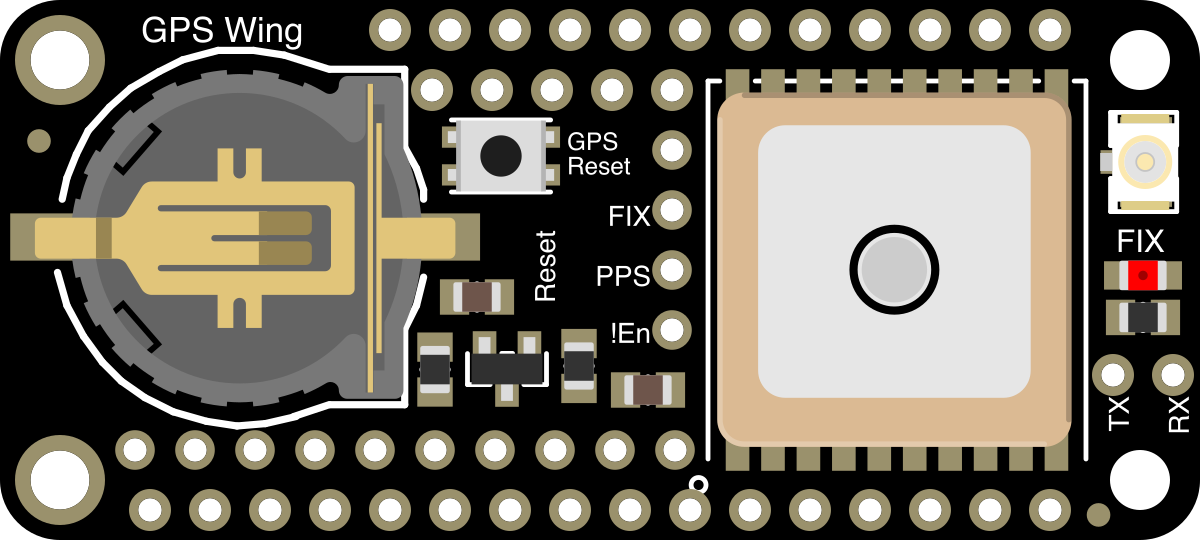
 Design with Adafruit GPS FeatherWing in Cirkit Designer
Introduction
The Adafruit GPS FeatherWing (Part ID: 3133) is a compact GPS module designed to seamlessly integrate with Adafruit Feather boards. It provides precise location data (latitude, longitude, altitude) and time information using UART communication. This module is based on the MTK3339 chipset, known for its high sensitivity and low power consumption, making it ideal for portable and IoT applications.
Explore Projects Built with Adafruit GPS FeatherWing
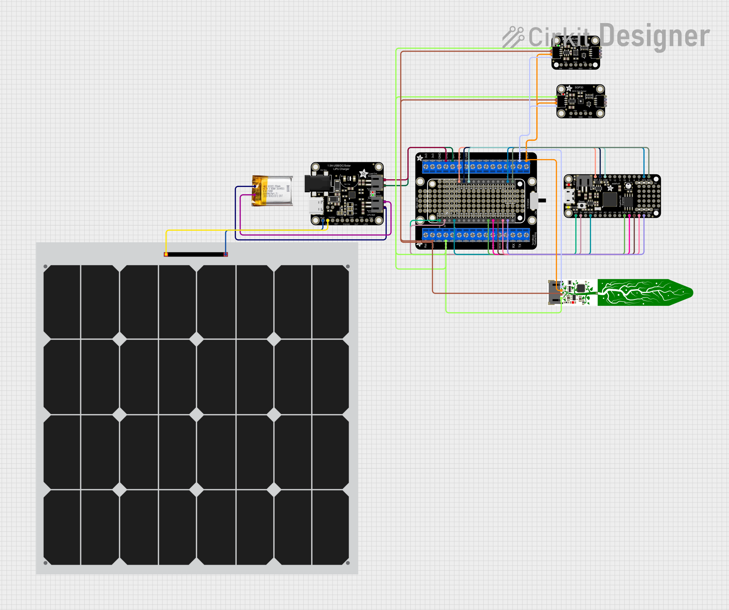 Open Project in Cirkit Designer
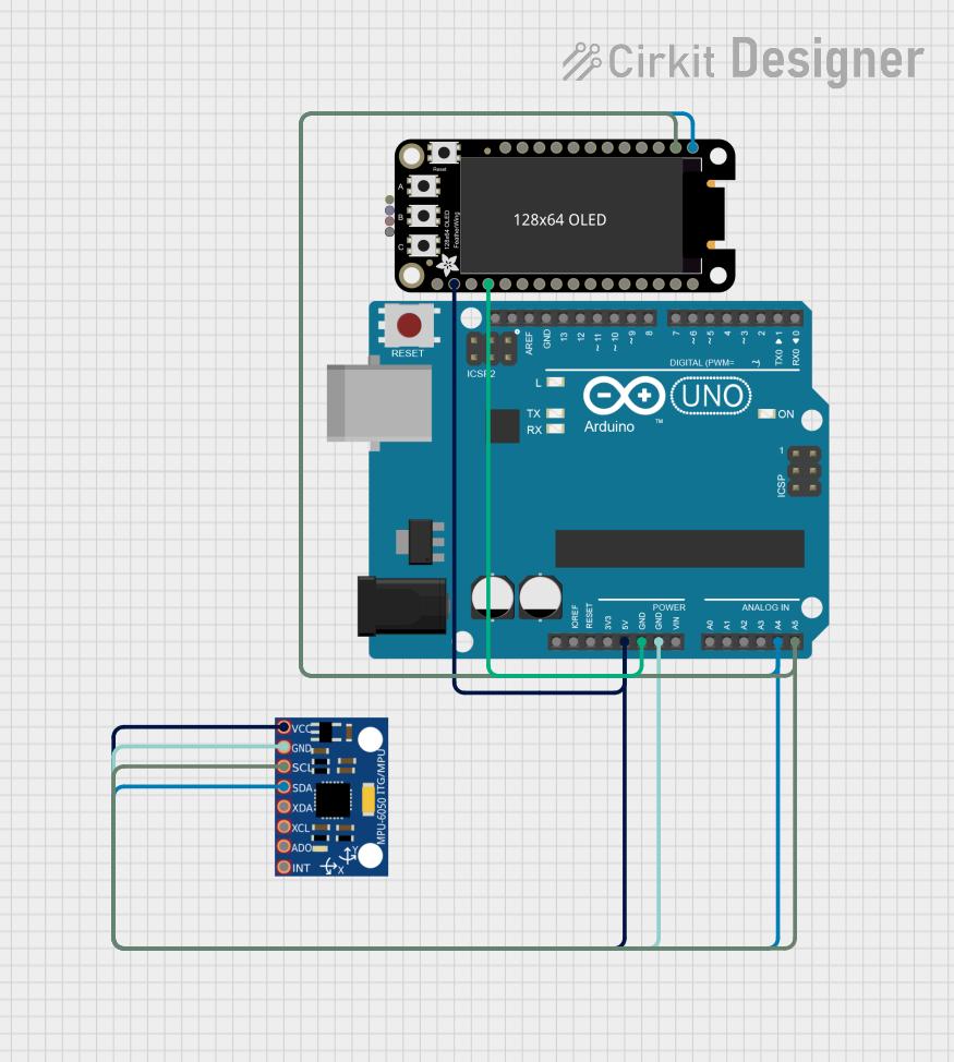 Open Project in Cirkit Designer
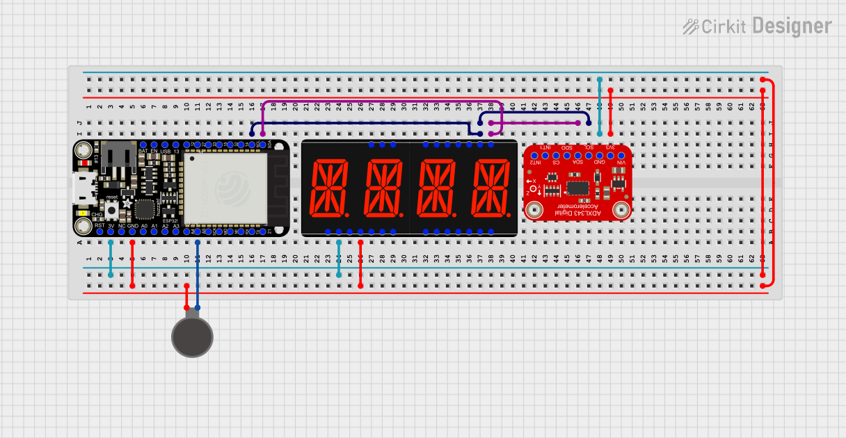 Open Project in Cirkit Designer
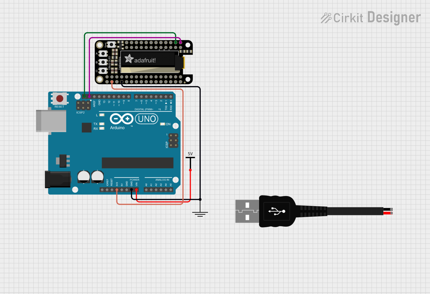 Open Project in Cirkit Designer
Explore Projects Built with Adafruit GPS FeatherWing
Open Project in Cirkit DesignerOpen Project in Cirkit DesignerOpen Project in Cirkit DesignerOpen Project in Cirkit DesignerCommon Applications and Use Cases
- GPS tracking for drones, robots, and vehicles
- Time synchronization for IoT devices
- Geolocation-based projects
- Outdoor navigation systems
- Data logging for environmental monitoring
Technical Specifications
The Adafruit GPS FeatherWing is built for ease of use and reliable performance. Below are its key technical details:
Key Technical Details
| Parameter | Specification |
|---|---|
| Chipset | MTK3339 |
| Communication Interface | UART (9600 baud default) |
| Input Voltage | 3.3V (Feather-compatible) |
| Current Consumption | ~20mA (tracking mode) |
| Position Accuracy | < 3 meters (CEP) |
| Time to First Fix (TTFF) | Cold Start: ~35 seconds, Hot Start: 1 second |
| Antenna | Built-in patch antenna + u.FL connector for external antenna |
| Dimensions | 50.8mm x 22.8mm x 8mm |
Pin Configuration and Descriptions
The Adafruit GPS FeatherWing has the following pin layout:
| Pin Name | Description |
|---|---|
| VIN | Power input (3.3V from Feather board) |
| GND | Ground connection |
| RX | UART Receive pin (connect to Feather TX) |
| TX | UART Transmit pin (connect to Feather RX) |
| PPS | Pulse-per-second output for precise timing (optional) |
| EN | Enable pin to turn the GPS module on/off (active high) |
| u.FL | Connector for an external GPS antenna (optional, for improved reception) |
Usage Instructions
How to Use the Adafruit GPS FeatherWing in a Circuit
Hardware Setup:
- Stack the GPS FeatherWing onto a compatible Adafruit Feather board.
- Ensure the VIN and GND pins are properly connected to the Feather board's power and ground.
- Connect the RX and TX pins of the GPS module to the TX and RX pins of the Feather board, respectively.
- If needed, attach an external GPS antenna to the u.FL connector for better reception.
Software Setup:
- Install the Adafruit GPS library in your Arduino IDE:
- Open the Arduino IDE.
- Go to Sketch > Include Library > Manage Libraries.
- Search for "Adafruit GPS" and install the library.
- Load the example sketch provided by the library to test the GPS module.
- Install the Adafruit GPS library in your Arduino IDE:
Powering the Module:
- The GPS FeatherWing is powered directly from the Feather board's 3.3V supply. Ensure the Feather board is powered via USB or a battery.
Important Considerations and Best Practices
- Antenna Placement: For optimal GPS signal reception, ensure the module or external antenna has a clear view of the sky.
- UART Configuration: The default baud rate is 9600. Ensure your Feather board's UART settings match this.
- Power Consumption: The module consumes ~20mA during operation. If using a battery, ensure it has sufficient capacity for your application.
- PPS Pin: Use the PPS pin for applications requiring precise timing, such as time synchronization.
Example Code for Arduino UNO
Below is an example sketch to read GPS data using the Adafruit GPS FeatherWing:
#include <Adafruit_GPS.h>
#include <SoftwareSerial.h>

// Create a SoftwareSerial connection for the GPS module
SoftwareSerial mySerial(8, 7); // RX, TX pins for Arduino UNO

// Initialize the GPS object
Adafruit_GPS GPS(&mySerial);

void setup() {
  Serial.begin(115200); // Start serial monitor for debugging
  mySerial.begin(9600); // Start GPS communication at 9600 baud

  // Initialize GPS module
  GPS.begin(9600);
  Serial.println("Adafruit GPS FeatherWing Test");

  // Configure GPS to output RMC (Recommended Minimum) and GGA (Fix Data) sentences
  GPS.sendCommand(PMTK_SET_NMEA_OUTPUT_RMCGGA);
  // Set update rate to 1 Hz (1 update per second)
  GPS.sendCommand(PMTK_SET_NMEA_UPDATE_1HZ);
}

void loop() {
  // Read data from the GPS module
  char c = GPS.read();
  if (c) {
    Serial.print(c); // Print raw GPS data to the serial monitor
  }

  // Check if a new NMEA sentence is available
  if (GPS.newNMEAreceived()) {
    if (!GPS.parse(GPS.lastNMEA())) {
      // If parsing fails, skip to the next loop iteration
      return;
    }
  }

  // Print parsed GPS data
  if (GPS.fix) {
    Serial.print("Location: ");
    Serial.print(GPS.latitude, 4);
    Serial.print(GPS.lat);
    Serial.print(", ");
    Serial.print(GPS.longitude, 4);
    Serial.println(GPS.lon);
  } else {
    Serial.println("Waiting for GPS fix...");
  }
}
Troubleshooting and FAQs
Common Issues and Solutions
No GPS Fix:
- Cause: Poor signal reception.
- Solution: Ensure the module or external antenna has a clear view of the sky. Avoid indoor use or areas with heavy obstructions.
No Data Output:
- Cause: Incorrect UART connections or baud rate mismatch.
- Solution: Verify that the RX and TX pins are correctly connected. Ensure the baud rate is set to 9600 in both hardware and software.
Intermittent Data:
- Cause: Insufficient power supply.
- Solution: Ensure the Feather board provides a stable 3.3V supply. If using a battery, check its charge level.
External Antenna Not Working:
- Cause: Improper connection or damaged antenna.
- Solution: Verify the u.FL connector is securely attached. Test with a known working antenna.
FAQs
Can I use this module with boards other than Adafruit Feather? Yes, but you may need to manually connect the pins and ensure compatibility with the 3.3V logic level.
What is the maximum update rate of the GPS module? The module supports up to 10 Hz update rate, but the default is 1 Hz.
Does the module work indoors? GPS signals are weak indoors. Use the module outdoors or near a window for best results.
How do I reset the GPS module? Power cycle the module by disconnecting and reconnecting the VIN pin or using the EN pin.
This concludes the documentation for the Adafruit GPS FeatherWing. For further assistance, refer to the official Adafruit documentation or community forums.