Cirkit Designer
Your all-in-one circuit design IDE
Home /
Component Documentation
How to Use ESP32-S3-WROOM: Examples, Pinouts, and Specs
Introduction
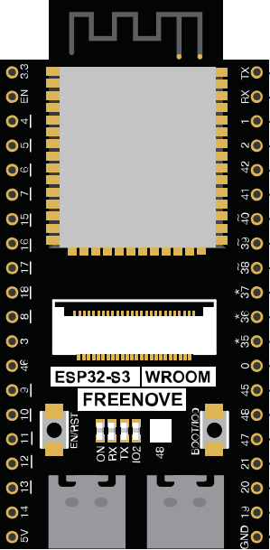
The ESP32-S3-WROOM, manufactured by FREENOVE (Part ID: FNK0085), is a powerful Wi-Fi and Bluetooth microcontroller module. It features a dual-core processor, designed specifically for IoT applications. This module is known for its high performance, low power consumption, and a rich set of peripherals, making it an ideal choice for a wide range of applications.
Explore Projects Built with ESP32-S3-WROOM
ESP32-Based GPS Tracker with SD Card Logging and Barometric Sensor

This circuit features an ESP32 Wroom Dev Kit as the main microcontroller, interfaced with an MPL3115A2 sensor for pressure and temperature readings, and a Neo 6M GPS module for location tracking. The ESP32 is also connected to an SD card reader for data logging purposes. A voltage regulator is used to step down the USB power supply to 3.3V, which powers the ESP32, the sensor, and the SD card reader.
ESP32-Based Multi-Sensor Health Monitoring System with Bluetooth Connectivity

This circuit features an ESP32-WROOM-32UE microcontroller as the central processing unit, interfacing with a variety of sensors and modules. It includes a MAX30100 pulse oximeter and heart-rate sensor, an MLX90614 infrared thermometer, an HC-05 Bluetooth module for wireless communication, and a Neo 6M GPS module for location tracking. All components are powered by a common voltage supply and are connected to specific GPIO pins on the ESP32 for data exchange, with the sensors using I2C communication and the modules using UART.
ESP32-Based Infrared Proximity Sensing System

This circuit features an ESP32 Wroom microcontroller connected to an Infrared Proximity Sensor. The ESP32's GPIO33 is interfaced with the sensor's output, allowing the microcontroller to read proximity data. The sensor is powered by the ESP32's 5V output, and both devices share a common ground.
ESP32 and SD Card Module Data Logger with Wi-Fi Connectivity
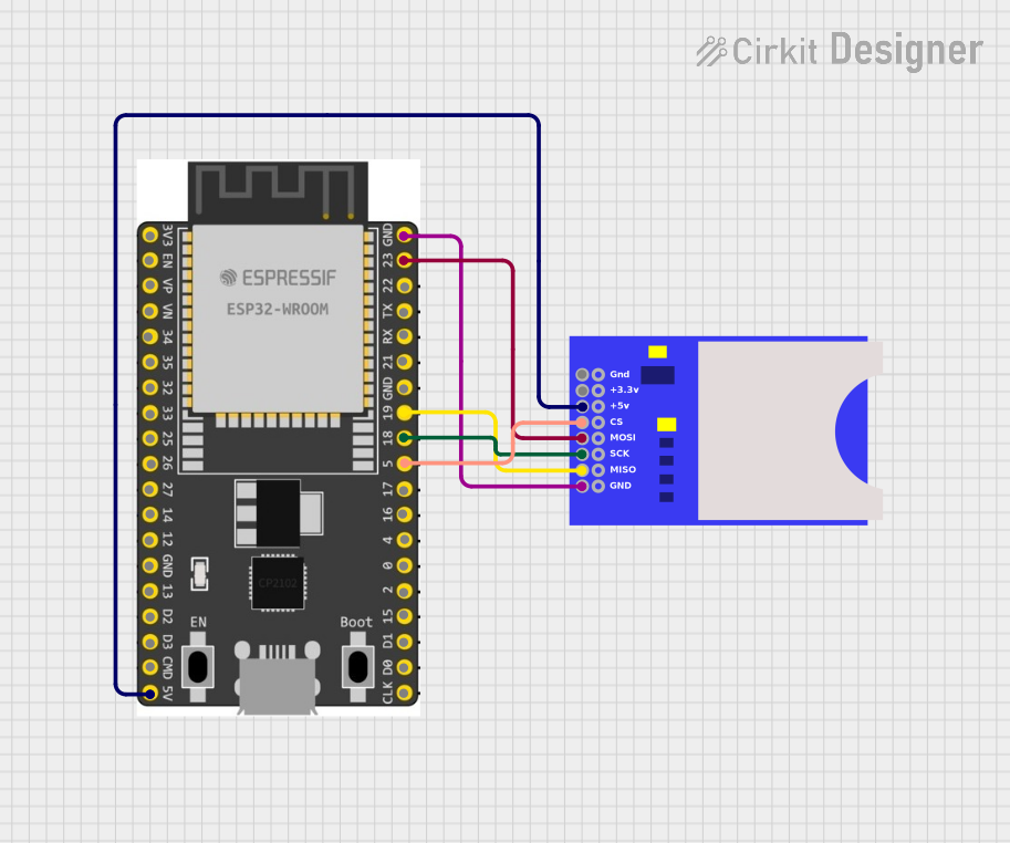
This circuit connects an ESP32 Wroom Dev Kit to an SD card module, enabling the ESP32 to read from and write to the SD card. The ESP32 provides power to the SD card module and communicates with it using SPI protocol through GPIO pins 23 (MOSI), 19 (MISO), 18 (SCK), and 5 (CS).
Explore Projects Built with ESP32-S3-WROOM
ESP32-Based GPS Tracker with SD Card Logging and Barometric Sensor
This circuit features an ESP32 Wroom Dev Kit as the main microcontroller, interfaced with an MPL3115A2 sensor for pressure and temperature readings, and a Neo 6M GPS module for location tracking. The ESP32 is also connected to an SD card reader for data logging purposes. A voltage regulator is used to step down the USB power supply to 3.3V, which powers the ESP32, the sensor, and the SD card reader.
ESP32-Based Multi-Sensor Health Monitoring System with Bluetooth Connectivity
This circuit features an ESP32-WROOM-32UE microcontroller as the central processing unit, interfacing with a variety of sensors and modules. It includes a MAX30100 pulse oximeter and heart-rate sensor, an MLX90614 infrared thermometer, an HC-05 Bluetooth module for wireless communication, and a Neo 6M GPS module for location tracking. All components are powered by a common voltage supply and are connected to specific GPIO pins on the ESP32 for data exchange, with the sensors using I2C communication and the modules using UART.
ESP32-Based Infrared Proximity Sensing System
This circuit features an ESP32 Wroom microcontroller connected to an Infrared Proximity Sensor. The ESP32's GPIO33 is interfaced with the sensor's output, allowing the microcontroller to read proximity data. The sensor is powered by the ESP32's 5V output, and both devices share a common ground.
ESP32 and SD Card Module Data Logger with Wi-Fi Connectivity
This circuit connects an ESP32 Wroom Dev Kit to an SD card module, enabling the ESP32 to read from and write to the SD card. The ESP32 provides power to the SD card module and communicates with it using SPI protocol through GPIO pins 23 (MOSI), 19 (MISO), 18 (SCK), and 5 (CS).
Common Applications and Use Cases
- IoT Devices: Smart home systems, industrial automation, and environmental monitoring.
- Wearable Electronics: Fitness trackers, smartwatches, and health monitoring devices.
- Wireless Communication: Wi-Fi and Bluetooth-enabled devices.
- Embedded Systems: Robotics, sensor networks, and data logging.
Technical Specifications
Key Technical Details
| Parameter | Value |
|---|---|
| Processor | Dual-core Xtensa LX7 |
| Clock Speed | Up to 240 MHz |
| Flash Memory | 4 MB |
| SRAM | 512 KB |
| Wi-Fi | 802.11 b/g/n |
| Bluetooth | Bluetooth 5.0 LE |
| Operating Voltage | 3.0V to 3.6V |
| I/O Voltage | 3.3V |
| Power Consumption | Ultra-low power consumption in deep sleep |
| Operating Temperature | -40°C to +85°C |
Pin Configuration and Descriptions
| Pin Number | Pin Name | Description |
|---|---|---|
| 1 | GND | Ground |
| 2 | 3V3 | 3.3V Power Supply |
| 3 | EN | Enable (Active High) |
| 4 | IO0 | GPIO0, used for boot mode selection |
| 5 | IO1 | GPIO1, UART0 TXD |
| 6 | IO2 | GPIO2, UART0 RXD |
| 7 | IO3 | GPIO3, UART1 TXD |
| 8 | IO4 | GPIO4, UART1 RXD |
| 9 | IO5 | GPIO5, SPI SCK |
| 10 | IO6 | GPIO6, SPI MISO |
| 11 | IO7 | GPIO7, SPI MOSI |
| 12 | IO8 | GPIO8, SPI CS |
| 13 | IO9 | GPIO9, I2C SCL |
| 14 | IO10 | GPIO10, I2C SDA |
| 15 | IO11 | GPIO11, ADC1 Channel 0 |
| 16 | IO12 | GPIO12, ADC1 Channel 1 |
| 17 | IO13 | GPIO13, ADC1 Channel 2 |
| 18 | IO14 | GPIO14, ADC1 Channel 3 |
| 19 | IO15 | GPIO15, ADC1 Channel 4 |
| 20 | IO16 | GPIO16, ADC1 Channel 5 |
| 21 | IO17 | GPIO17, ADC1 Channel 6 |
| 22 | IO18 | GPIO18, ADC1 Channel 7 |
| 23 | IO19 | GPIO19, ADC1 Channel 8 |
| 24 | IO20 | GPIO20, ADC1 Channel 9 |
| 25 | IO21 | GPIO21, ADC2 Channel 0 |
| 26 | IO22 | GPIO22, ADC2 Channel 1 |
| 27 | IO23 | GPIO23, ADC2 Channel 2 |
| 28 | IO24 | GPIO24, ADC2 Channel 3 |
| 29 | IO25 | GPIO25, ADC2 Channel 4 |
| 30 | IO26 | GPIO26, ADC2 Channel 5 |
| 31 | IO27 | GPIO27, ADC2 Channel 6 |
| 32 | IO28 | GPIO28, ADC2 Channel 7 |
| 33 | IO29 | GPIO29, ADC2 Channel 8 |
| 34 | IO30 | GPIO30, ADC2 Channel 9 |
| 35 | IO31 | GPIO31, DAC1 |
| 36 | IO32 | GPIO32, DAC2 |
| 37 | IO33 | GPIO33, Touch Sensor 0 |
| 38 | IO34 | GPIO34, Touch Sensor 1 |
| 39 | IO35 | GPIO35, Touch Sensor 2 |
| 40 | IO36 | GPIO36, Touch Sensor 3 |
| 41 | IO37 | GPIO37, Touch Sensor 4 |
| 42 | IO38 | GPIO38, Touch Sensor 5 |
| 43 | IO39 | GPIO39, Touch Sensor 6 |
| 44 | IO40 | GPIO40, Touch Sensor 7 |
| 45 | IO41 | GPIO41, Touch Sensor 8 |
| 46 | IO42 | GPIO42, Touch Sensor 9 |
| 47 | IO43 | GPIO43, Touch Sensor 10 |
| 48 | IO44 | GPIO44, Touch Sensor 11 |
Usage Instructions
How to Use the Component in a Circuit
- Power Supply: Connect the 3V3 pin to a 3.3V power source and the GND pin to ground.
- Enable Pin: Connect the EN pin to a high logic level (3.3V) to enable the module.
- GPIO Pins: Use the GPIO pins for digital input/output operations. Refer to the pin configuration table for specific functions.
- Communication Interfaces: Utilize UART, SPI, and I2C interfaces for communication with other devices.
- Analog Inputs: Use the ADC pins for analog-to-digital conversion.
- Touch Sensors: Connect touch sensors to the designated GPIO pins for capacitive touch sensing.
Important Considerations and Best Practices
- Power Supply: Ensure a stable 3.3V power supply to avoid damage to the module.
- Boot Mode Selection: Use GPIO0 for boot mode selection. Pull it low during reset to enter bootloader mode.
- Antenna Placement: For optimal Wi-Fi and Bluetooth performance, place the module away from metal objects and other sources of interference.
- Deep Sleep Mode: Utilize deep sleep mode to minimize power consumption in battery-powered applications.
Example Code for Arduino UNO
#include <WiFi.h>

// Replace with your network credentials
const char* ssid = "your_SSID";
const char* password = "your_PASSWORD";

void setup() {
  Serial.begin(115200);

  // Connect to Wi-Fi
  WiFi.begin(ssid, password);

  // Wait for connection
  while (WiFi.status() != WL_CONNECTED) {
    delay(1000);
    Serial.println("Connecting to WiFi...");
  }

  Serial.println("Connected to WiFi");
}

void loop() {
  // Your code here
}
Troubleshooting and FAQs
Common Issues Users Might Face
Module Not Powering On:
- Solution: Check the power supply connections and ensure a stable 3.3V source.
Wi-Fi Connection Issues:
- Solution: Verify the SSID and password. Ensure the module is within range of the Wi-Fi router.
Boot Mode Issues:
- Solution: Ensure GPIO0 is pulled low during reset to enter bootloader mode.
High Power Consumption:
- Solution: Utilize deep sleep mode to reduce power consumption in battery-powered applications.
Solutions and Tips for Troubleshooting
- Check Connections: Ensure all connections are secure and correct according to the pin configuration.
- Use Serial Monitor: Utilize the Serial Monitor for debugging and checking the status of the module.
- Firmware Updates: Keep the module's firmware updated to the latest version for optimal performance and bug fixes.
- Consult Documentation: Refer to the official FREENOVE documentation for detailed information and advanced troubleshooting.
By following this documentation, users can effectively utilize the ESP32-S3-WROOM module in their projects, ensuring optimal performance and reliability.