
How to Use RGB Led Strip Controller: Examples, Pinouts, and Specs
 Design with RGB Led Strip Controller in Cirkit Designer
Introduction
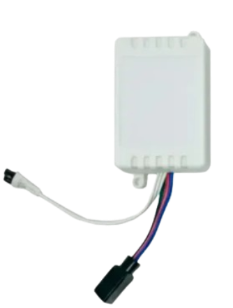
The RGB LED Strip Controller (Manufacturer: Generic, Part ID: Controller) is a versatile device designed to control the color, brightness, and lighting effects of RGB LED strips. It enables users to create dynamic lighting setups with customizable modes, colors, and brightness levels. This controller is ideal for applications such as home decoration, ambient lighting, signage, and stage lighting.
Explore Projects Built with RGB Led Strip Controller
 Open Project in Cirkit Designer
 Open Project in Cirkit Designer
 Open Project in Cirkit Designer
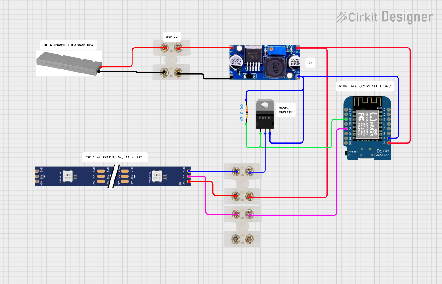 Open Project in Cirkit Designer
Explore Projects Built with RGB Led Strip Controller
Open Project in Cirkit DesignerOpen Project in Cirkit DesignerOpen Project in Cirkit DesignerOpen Project in Cirkit DesignerCommon Applications and Use Cases
- Home Decoration: Enhance the ambiance of living spaces with customizable lighting.
- Retail and Signage: Highlight products or create eye-catching displays.
- Entertainment: Add dynamic lighting effects to gaming setups, parties, or events.
- Stage Lighting: Provide vibrant and programmable lighting for performances.
Technical Specifications
Key Technical Details
| Parameter | Specification |
|---|---|
| Input Voltage | 5V to 24V DC |
| Output Channels | 3 (Red, Green, Blue) |
| Maximum Output Current | 6A (2A per channel) |
| Control Modes | IR Remote, Bluetooth, or Wi-Fi (varies by model) |
| Supported LED Types | RGB LED strips (common anode) |
| Operating Temperature | -20°C to 60°C |
| Dimensions | 50mm x 35mm x 15mm |
Pin Configuration and Descriptions
The RGB LED Strip Controller typically has the following pin configuration:
| Pin Name | Description |
|---|---|
| V+ | Positive voltage input (5V to 24V DC) |
| R | Red channel output (connect to LED strip) |
| G | Green channel output (connect to LED strip) |
| B | Blue channel output (connect to LED strip) |
| GND | Ground connection |
| IR Sensor | Infrared sensor input for remote control (if applicable) |
Usage Instructions
How to Use the Component in a Circuit
- Power Supply: Connect a DC power supply (5V to 24V) to the
V+andGNDpins of the controller. Ensure the voltage matches the requirements of your RGB LED strip. - LED Strip Connection: Connect the
R,G, andBpins of the controller to the corresponding terminals on the RGB LED strip. Connect the common anode of the LED strip to theV+pin. - Control Input: If using an IR remote, ensure the IR sensor is positioned to receive signals. For Bluetooth or Wi-Fi models, pair the controller with the corresponding app or device.
- Operation: Use the remote or app to adjust the color, brightness, and effects of the LED strip.
Important Considerations and Best Practices
- Voltage Matching: Ensure the power supply voltage matches the operating voltage of the LED strip and controller.
- Current Limitations: Do not exceed the maximum current rating of 2A per channel to avoid overheating or damage.
- Heat Dissipation: If operating at high currents, ensure proper ventilation or heat dissipation for the controller.
- Polarity: Double-check all connections to avoid reverse polarity, which can damage the controller or LED strip.
Example: Connecting to an Arduino UNO
The RGB LED Strip Controller can also be controlled via an Arduino UNO using PWM signals. Below is an example code snippet:
// Example code to control an RGB LED strip using an Arduino UNO
// Connect the R, G, and B pins of the controller to Arduino PWM pins 9, 10, and 11

#define RED_PIN 9    // PWM pin connected to the Red channel
#define GREEN_PIN 10 // PWM pin connected to the Green channel
#define BLUE_PIN 11  // PWM pin connected to the Blue channel

void setup() {
  pinMode(RED_PIN, OUTPUT);   // Set Red pin as output
  pinMode(GREEN_PIN, OUTPUT); // Set Green pin as output
  pinMode(BLUE_PIN, OUTPUT);  // Set Blue pin as output
}

void loop() {
  // Example: Fade through Red, Green, and Blue colors
  for (int i = 0; i <= 255; i++) {
    analogWrite(RED_PIN, i);   // Increase Red brightness
    analogWrite(GREEN_PIN, 255 - i); // Decrease Green brightness
    analogWrite(BLUE_PIN, 0);  // Keep Blue off
    delay(10); // Small delay for smooth fading
  }
}
Troubleshooting and FAQs
Common Issues and Solutions
LED Strip Not Lighting Up:
- Cause: Incorrect wiring or insufficient power supply.
- Solution: Verify all connections and ensure the power supply voltage matches the LED strip's requirements.
Flickering or Dim LEDs:
- Cause: Insufficient current or loose connections.
- Solution: Use a power supply with adequate current capacity and check all connections.
Controller Overheating:
- Cause: Exceeding the maximum current rating.
- Solution: Reduce the number of LEDs or use a controller with a higher current rating.
Remote Not Working:
- Cause: Dead batteries or obstructed IR sensor.
- Solution: Replace the remote batteries and ensure a clear line of sight to the IR sensor.
FAQs
Q: Can I use this controller with addressable LED strips?
A: No, this controller is designed for non-addressable RGB LED strips with a common anode.Q: What is the maximum length of LED strip I can connect?
A: This depends on the power supply and current rating. Ensure the total current does not exceed 6A.Q: Can I control the LED strip with my smartphone?
A: Yes, if the controller supports Bluetooth or Wi-Fi. Check the model specifications.Q: Is it safe to use outdoors?
A: Only if the controller is housed in a waterproof enclosure. Otherwise, it is designed for indoor use.