Cirkit Designer Logo
Cirkit Designer
Your all-in-one circuit design IDE
Home / 
Component Documentation

How to Use Inductor: Examples, Pinouts, and Specs

Image of Inductor
Cirkit Designer LogoDesign with Inductor in Cirkit Designer

Introduction

An inductor, also known as a coil or reactor, is a passive electronic component designed to resist changes in current. Inductors are characterized by their ability to store energy in a magnetic field when electrical current flows through them. They are commonly used in a variety of applications including power supplies, radio frequency circuits, and as filtering devices in audio electronics.

Explore Projects Built with Inductor

Use Cirkit Designer to design, explore, and prototype these projects online. Some projects support real-time simulation. Click "Open Project" to start designing instantly!
Voltage Regulated Transformer Power Supply Circuit
Image of revisi 3 : A project utilizing Inductor in a practical application
This circuit appears to be a power supply circuit with a transformer connected to a 12V battery for voltage step-up or step-down. It includes a rectification stage with a 1N4007 diode, smoothing with an electrolytic capacitor, and regulation using a Zener diode. Additionally, there are inductors for filtering and a BT139 600 triac for controlling AC power, possibly for dimming or switching applications.
Cirkit Designer LogoOpen Project in Cirkit Designer
Function Generator and Oscilloscope-Based RLC Circuit Analysis
Image of lab 9: butterworth band pass circuit configuration: A project utilizing Inductor in a practical application
This circuit is an RLC (Resistor-Inductor-Capacitor) network driven by a function generator and monitored using a mixed signal oscilloscope. The function generator provides the input signal, while the oscilloscope measures the response across various components, allowing for analysis of the circuit's frequency response and transient behavior.
Cirkit Designer LogoOpen Project in Cirkit Designer
Arduino-Controlled Relay with FlySky Receiver for Remote Switching
Image of wire less ignitor: A project utilizing Inductor in a practical application
This circuit uses an Arduino UNO to control a 5V relay module, which in turn can switch a higher voltage circuit connected to a 12V battery through an inductor. The relay is actuated by a digital output from the Arduino (D8), and the Arduino is also interfaced with a FLYSKY FS-IA6 receiver (via D7) to potentially receive remote commands. The relay's normally open (N.O.) contact is connected in series with the inductor, and the common (COM) contact is connected to the positive terminal of the 12V battery, allowing the inductor to be energized when the relay is activated.
Cirkit Designer LogoOpen Project in Cirkit Designer
Function Generator and Oscilloscope-Based RLC Circuit Analysis
Image of lab 8: butterworth high pass circuit configuration: A project utilizing Inductor in a practical application
This circuit is an RLC (Resistor-Inductor-Capacitor) network driven by a function generator and monitored using a mixed signal oscilloscope. The function generator provides the input signal, while the oscilloscope captures the response across various components, allowing for analysis of the circuit's behavior.
Cirkit Designer LogoOpen Project in Cirkit Designer

Explore Projects Built with Inductor

Use Cirkit Designer to design, explore, and prototype these projects online. Some projects support real-time simulation. Click "Open Project" to start designing instantly!
Image of revisi 3 : A project utilizing Inductor in a practical application
Voltage Regulated Transformer Power Supply Circuit
This circuit appears to be a power supply circuit with a transformer connected to a 12V battery for voltage step-up or step-down. It includes a rectification stage with a 1N4007 diode, smoothing with an electrolytic capacitor, and regulation using a Zener diode. Additionally, there are inductors for filtering and a BT139 600 triac for controlling AC power, possibly for dimming or switching applications.
Cirkit Designer LogoOpen Project in Cirkit Designer
Image of lab 9: butterworth band pass circuit configuration: A project utilizing Inductor in a practical application
Function Generator and Oscilloscope-Based RLC Circuit Analysis
This circuit is an RLC (Resistor-Inductor-Capacitor) network driven by a function generator and monitored using a mixed signal oscilloscope. The function generator provides the input signal, while the oscilloscope measures the response across various components, allowing for analysis of the circuit's frequency response and transient behavior.
Cirkit Designer LogoOpen Project in Cirkit Designer
Image of wire less ignitor: A project utilizing Inductor in a practical application
Arduino-Controlled Relay with FlySky Receiver for Remote Switching
This circuit uses an Arduino UNO to control a 5V relay module, which in turn can switch a higher voltage circuit connected to a 12V battery through an inductor. The relay is actuated by a digital output from the Arduino (D8), and the Arduino is also interfaced with a FLYSKY FS-IA6 receiver (via D7) to potentially receive remote commands. The relay's normally open (N.O.) contact is connected in series with the inductor, and the common (COM) contact is connected to the positive terminal of the 12V battery, allowing the inductor to be energized when the relay is activated.
Cirkit Designer LogoOpen Project in Cirkit Designer
Image of lab 8: butterworth high pass circuit configuration: A project utilizing Inductor in a practical application
Function Generator and Oscilloscope-Based RLC Circuit Analysis
This circuit is an RLC (Resistor-Inductor-Capacitor) network driven by a function generator and monitored using a mixed signal oscilloscope. The function generator provides the input signal, while the oscilloscope captures the response across various components, allowing for analysis of the circuit's behavior.
Cirkit Designer LogoOpen Project in Cirkit Designer

Common Applications and Use Cases

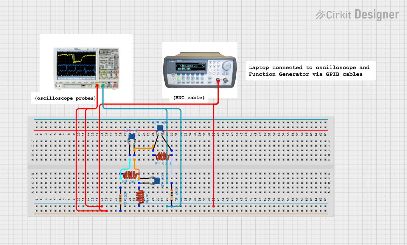
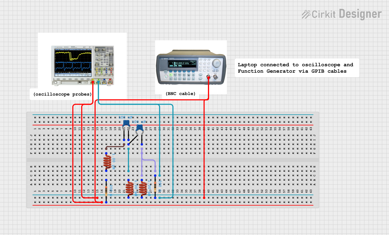
  • LC Filters: In combination with capacitors to form LC filters for signal processing.
  • Chokes: To block higher-frequency AC signals while passing DC or lower-frequency signals.
  • Energy Storage: In switch-mode power supplies to store energy temporarily.
  • Transformers: Paired with other inductors to form transformers for voltage step-up or step-down.
  • Inductive Sensors: For proximity sensing and metal detection.
  • EMI Suppression: To reduce electromagnetic interference in electronic circuits.

Technical Specifications

Key Technical Details

  • Inductance (L): Measured in henries (H), indicates the amount of energy stored for a given current.
  • Rated Current (I): The maximum current the inductor can carry without saturation.
  • DC Resistance (DCR): The resistance of the wire winding, affecting power loss.
  • Self-Resonant Frequency (SRF): The frequency at which the inductor behaves as a resonator.
  • Quality Factor (Q): A dimensionless parameter that describes the inductor's efficiency.
  • Saturation Current (Isat): The current at which the inductor's inductance begins to decrease significantly.
  • Temperature Rating: The range of operating temperatures for the inductor.

Pin Configuration and Descriptions

Inductors typically have two terminals. Below is a table describing the pin configuration for a through-hole inductor:

Pin Number Description
1 First terminal (input or output, non-polarized)
2 Second terminal (input or output, non-polarized)

Surface-mount inductors will have a similar two-terminal configuration but will be designed for soldering directly onto a printed circuit board.

Usage Instructions

How to Use the Inductor in a Circuit

  1. Identify Inductance Value: Determine the required inductance for your application.
  2. Circuit Placement: Connect the inductor in series with the circuit for current control or in parallel with a capacitor for filtering.
  3. Orientation: Since inductors are non-polarized, they can be connected in either direction.
  4. Soldering: For through-hole inductors, use a soldering iron to attach the leads to the PCB. For surface-mount types, use reflow soldering techniques.

Important Considerations and Best Practices

  • Avoid Saturation: Ensure the operating current is below the inductor's saturation current.
  • Minimize Losses: Select an inductor with a low DC resistance to reduce power losses.
  • Thermal Management: Be aware of the temperature rating and provide adequate cooling if necessary.
  • Physical Placement: Keep inductors away from components sensitive to magnetic fields.

Troubleshooting and FAQs

Common Issues Users Might Face

  • Overheating: Caused by excessive current or a high DC resistance.
  • Saturation: Occurs when the inductor is subjected to a current above its rated saturation current.
  • Noise: Inductors can introduce electromagnetic noise into a circuit if not properly shielded.

Solutions and Tips for Troubleshooting

  • Check Current Levels: Ensure the current through the inductor does not exceed its rated current.
  • Inspect for Physical Damage: Look for signs of overheating or damaged windings.
  • Measure Inductance: Use an LCR meter to verify the inductance is within specifications.

FAQs

Q: Can I replace an inductor with a higher inductance value? A: It depends on the application. In filters, a higher inductance will change the cutoff frequency. In power applications, it may affect the efficiency and regulation.

Q: What happens if an inductor is placed near another inductor or transformer? A: Magnetic coupling may occur, which can lead to unwanted interference between the components.

Q: How do I choose the right inductor for my application? A: Consider the required inductance, current rating, DC resistance, quality factor, and size constraints for your specific application.

Example Code for Arduino UNO

Below is an example of how to use an inductor in a simple LC filter circuit with an Arduino UNO to filter a PWM signal.

// Define the PWM pin and frequency
const int pwmPin = 3; // PWM output pin
const int pwmFrequency = 490; // PWM frequency in Hz

void setup() {
  // Set the PWM pin as an output
  pinMode(pwmPin, OUTPUT);
  // Start the PWM signal
  analogWrite(pwmPin, 128); // Set a 50% duty cycle
}

void loop() {
  // The inductor in the LC filter circuit will smooth out the PWM signal.
  // No additional code is needed for the inductor itself.
  // The rest of the code would depend on the specific application.
}

Note: This code assumes that an inductor and a capacitor are already connected in the correct configuration on a breadboard or PCB to form an LC filter. The inductor does not require any direct interaction through code, as its behavior is purely electrical.