
How to Use SO-36w: Examples, Pinouts, and Specs
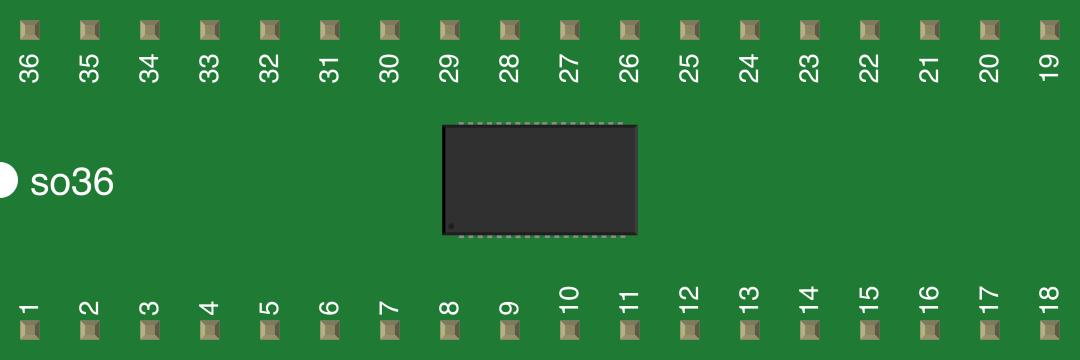
 Design with SO-36w in Cirkit Designer
Introduction
The SO-36w is a surface-mount package type designed for integrated circuits (ICs). It features 36 pins arranged in a narrow outline, making it ideal for high-density applications where space is a critical factor. This package type is widely used in modern electronics due to its compact size and compatibility with automated assembly processes.
Explore Projects Built with SO-36w
 Open Project in Cirkit Designer
 Open Project in Cirkit Designer
 Open Project in Cirkit Designer
 Open Project in Cirkit Designer
Explore Projects Built with SO-36w
Open Project in Cirkit DesignerOpen Project in Cirkit DesignerOpen Project in Cirkit DesignerOpen Project in Cirkit DesignerCommon Applications and Use Cases
- Microcontrollers and digital signal processors (DSPs)
- Power management ICs
- Communication modules
- Consumer electronics, such as smartphones and tablets
- Automotive electronics
- Industrial control systems
Technical Specifications
Key Technical Details
| Parameter | Value/Description |
|---|---|
| Package Type | SO-36w (Small Outline, 36 pins, wide) |
| Pin Count | 36 |
| Pitch (Pin-to-Pin) | 1.27 mm |
| Body Width | 7.5 mm |
| Body Length | 12.8 mm |
| Maximum Height | 2.65 mm |
| Thermal Resistance | Varies by IC; typically 30-50°C/W |
| Operating Temperature | -40°C to +125°C |
| Mounting Type | Surface Mount Technology (SMT) |
Pin Configuration and Descriptions
The pin configuration of the SO-36w package depends on the specific IC housed within it. Below is a generic example of a pinout for a microcontroller in an SO-36w package:
| Pin Number | Pin Name | Description |
|---|---|---|
| 1 | VCC | Power supply input |
| 2 | GND | Ground |
| 3-8 | GPIO1-GPIO6 | General-purpose input/output pins |
| 9 | RESET | Reset input |
| 10-15 | ADC1-ADC6 | Analog-to-digital converter inputs |
| 16-20 | PWM1-PWM5 | Pulse-width modulation outputs |
| 21-25 | UART_TX/RX | UART communication pins |
| 26-30 | SPI_MOSI/MISO | SPI communication pins |
| 31-36 | I2C_SCL/SDA | I2C communication pins |
Note: The actual pinout may vary depending on the IC manufacturer and its intended functionality. Always refer to the specific IC datasheet for accurate pin descriptions.
Usage Instructions
How to Use the SO-36w in a Circuit
- PCB Design: Ensure your PCB layout matches the SO-36w footprint. The pin pitch is 1.27 mm, and the body dimensions are 7.5 mm x 12.8 mm.
- Soldering: Use reflow soldering for mounting the SO-36w package. Ensure the solder paste is applied evenly to avoid bridging between pins.
- Power Supply: Verify that the power supply voltage matches the IC's requirements. Connect VCC and GND pins properly.
- Signal Connections: Connect the signal pins (e.g., GPIO, ADC, UART) to the appropriate components in your circuit.
- Testing: After assembly, test the circuit for proper functionality. Check for soldering defects, such as cold joints or shorts.
Important Considerations and Best Practices
- Thermal Management: Ensure adequate thermal dissipation, especially for high-power ICs. Use thermal vias or a heat sink if necessary.
- ESD Protection: Handle the SO-36w package with care to prevent electrostatic discharge (ESD) damage. Use an ESD-safe workstation.
- Pin Alignment: Double-check the orientation of the IC before soldering. Misalignment can cause circuit failure.
- Cleaning: After soldering, clean the PCB to remove flux residues that may cause corrosion or short circuits.
Example: Connecting an SO-36w Microcontroller to an Arduino UNO
If the SO-36w package houses a microcontroller, you can interface it with an Arduino UNO for testing or prototyping. Below is an example of Arduino code to communicate with an SO-36w microcontroller via UART:
// Example: Arduino UNO communicating with an SO-36w microcontroller via UART

#include <SoftwareSerial.h>

// Define RX and TX pins for SoftwareSerial
SoftwareSerial mySerial(10, 11); // RX = pin 10, TX = pin 11

void setup() {
  Serial.begin(9600); // Start the hardware serial communication
  mySerial.begin(9600); // Start the software serial communication

  Serial.println("Arduino is ready to communicate with SO-36w microcontroller.");
}

void loop() {
  // Send data to the SO-36w microcontroller
  mySerial.println("Hello, SO-36w!");

  // Check if data is available from the SO-36w microcontroller
  if (mySerial.available()) {
    String receivedData = mySerial.readString();
    Serial.print("Received from SO-36w: ");
    Serial.println(receivedData);
  }

  delay(1000); // Wait for 1 second before sending the next message
}
Note: Ensure the SO-36w microcontroller's UART pins are connected to the Arduino UNO's RX and TX pins (via level shifters if necessary).
Troubleshooting and FAQs
Common Issues Users Might Face
- Soldering Defects: Pins may not be soldered properly, leading to poor connections.
- Solution: Inspect the solder joints under a microscope and reflow solder if necessary.
- Incorrect Pin Connections: Misaligned or incorrect pin connections can cause circuit failure.
- Solution: Double-check the pinout and ensure proper connections.
- Overheating: The IC may overheat due to insufficient thermal dissipation.
- Solution: Add thermal vias or a heat sink to improve heat dissipation.
- ESD Damage: The IC may be damaged due to improper handling.
- Solution: Use ESD-safe tools and follow proper handling procedures.
FAQs
Q1: Can I hand-solder an SO-36w package?
A1: While it is possible to hand-solder an SO-36w package, it is challenging due to the small pin pitch. Reflow soldering is recommended for best results.
Q2: How do I clean flux residue after soldering?
A2: Use isopropyl alcohol (IPA) and a soft brush to clean the PCB. Ensure the board is completely dry before powering it on.
Q3: What is the maximum current the SO-36w package can handle?
A3: The maximum current depends on the IC housed within the SO-36w package. Refer to the IC's datasheet for specific details.
Q4: Can I use the SO-36w package for high-frequency applications?
A4: Yes, the SO-36w package is suitable for high-frequency applications, provided the PCB layout minimizes parasitic inductance and capacitance.
By following this documentation, you can effectively integrate and troubleshoot the SO-36w package in your electronic designs.