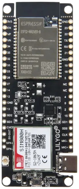
How to Use Lilygo ESP32 T-Call: Examples, Pinouts, and Specs
Introduction
The Lilygo ESP32 T-Call is a versatile development board that combines the powerful ESP32 microcontroller with GSM/GPRS capabilities. This makes it an excellent choice for IoT applications requiring cellular connectivity, such as remote monitoring, asset tracking, and smart agriculture. The board supports a wide range of communication protocols, including Wi-Fi, Bluetooth, and GSM, enabling seamless integration into various IoT ecosystems.
Explore Projects Built with Lilygo ESP32 T-Call
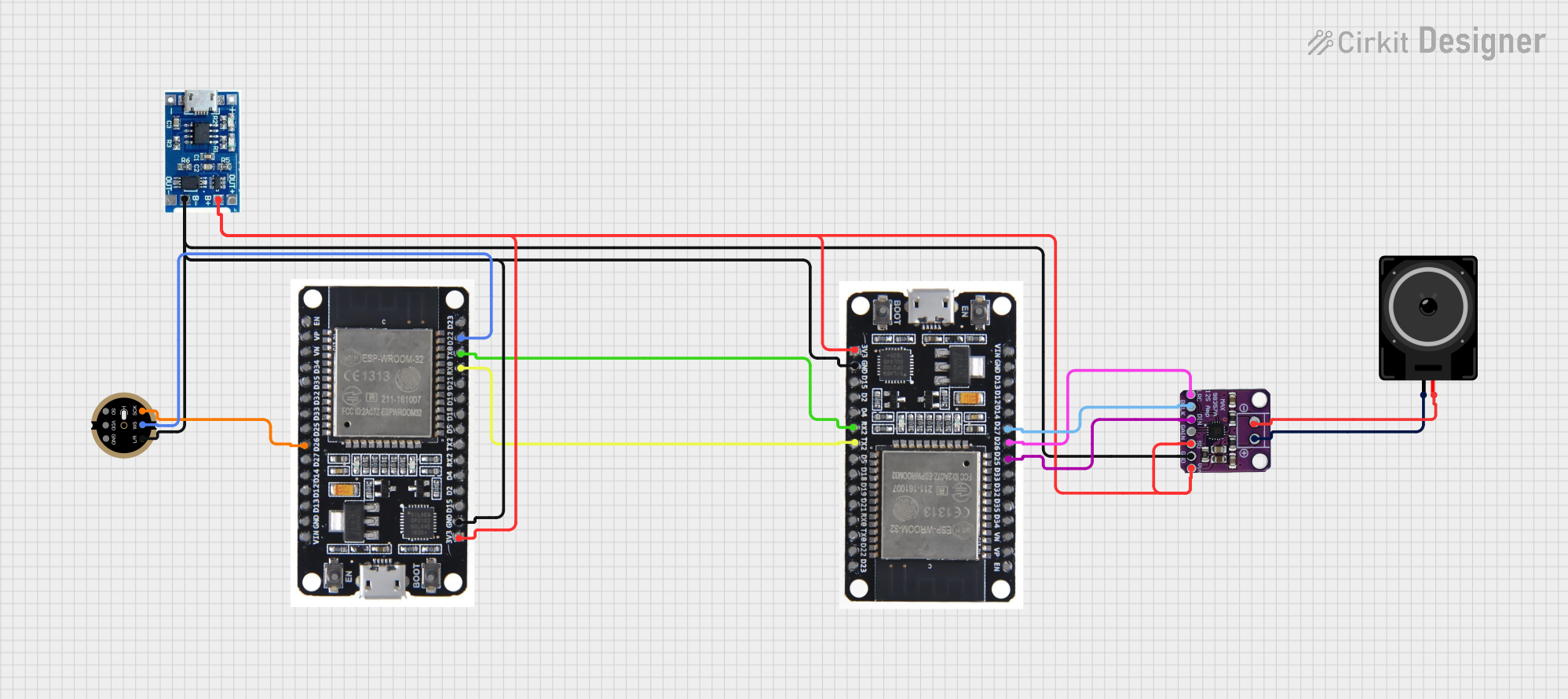

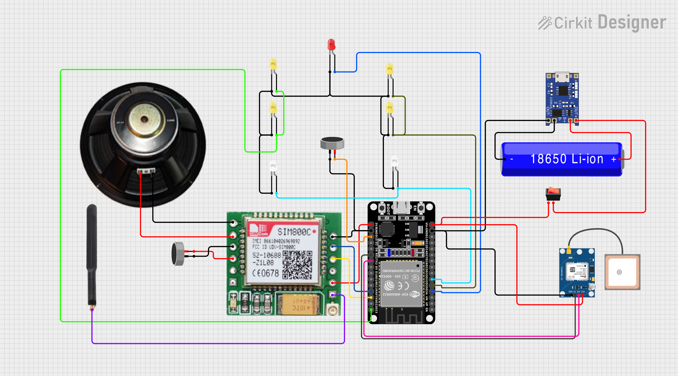
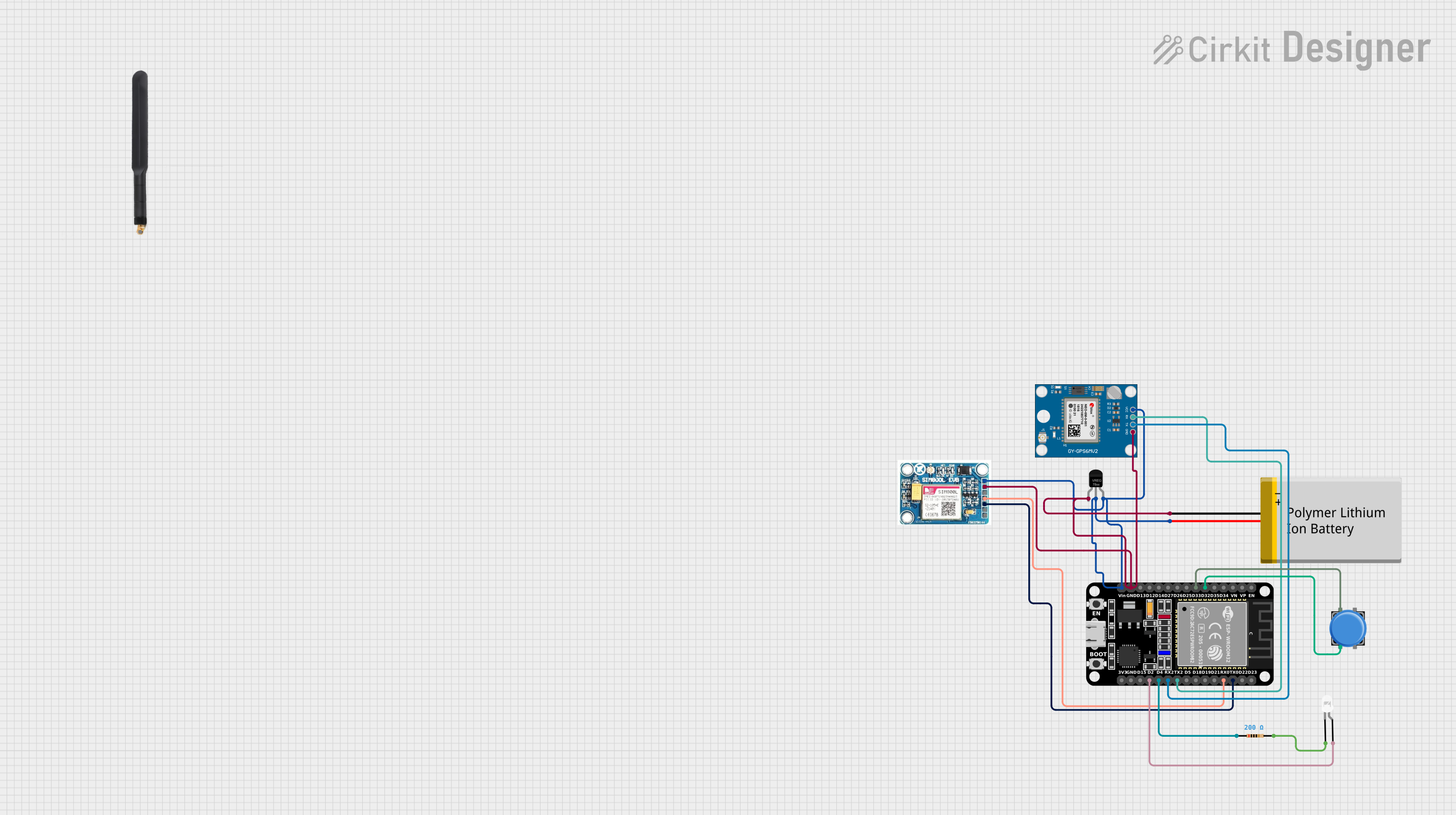
Explore Projects Built with Lilygo ESP32 T-Call
Common Applications and Use Cases
- Remote data logging and monitoring
- GPS tracking and asset management
- Smart agriculture and environmental monitoring
- Home automation with cellular backup
- IoT projects in areas with limited Wi-Fi coverage
Technical Specifications
The Lilygo ESP32 T-Call is designed to provide robust performance for IoT applications. Below are its key technical specifications:
Key Technical Details
| Parameter | Specification |
|---|---|
| Microcontroller | ESP32 Dual-Core Processor |
| Flash Memory | 4 MB |
| RAM | 520 KB SRAM |
| GSM Module | SIM800L |
| GSM Frequency Bands | Quad-band: 850/900/1800/1900 MHz |
| Wi-Fi | 802.11 b/g/n |
| Bluetooth | BLE 4.2 |
| Operating Voltage | 3.3V |
| Input Voltage Range | 5V (via USB) |
| Power Consumption | ~80 mA (idle), ~250 mA (GSM active) |
| Antenna | External GSM antenna (included) |
| SIM Card Slot | Micro SIM |
| Dimensions | 51 x 25.5 mm |
Pin Configuration and Descriptions
The Lilygo ESP32 T-Call features a variety of pins for interfacing with peripherals. Below is the pinout description:
| Pin Name | Function | Description |
|---|---|---|
| 3V3 | Power Supply | 3.3V output for powering external devices |
| GND | Ground | Common ground |
| TXD | UART Transmit | Transmit data to external devices |
| RXD | UART Receive | Receive data from external devices |
| GPIO4 | General Purpose I/O | Configurable digital I/O pin |
| GPIO5 | General Purpose I/O | Configurable digital I/O pin |
| GPIO21 | SDA (I2C) | Data line for I2C communication |
| GPIO22 | SCL (I2C) | Clock line for I2C communication |
| GPIO23 | SPI MOSI | Master Out Slave In for SPI |
| GPIO19 | SPI MISO | Master In Slave Out for SPI |
| GPIO18 | SPI SCK | Clock line for SPI communication |
| GPIO16 | GSM Power Key | Used to power on/off the SIM800L module |
Usage Instructions
The Lilygo ESP32 T-Call is straightforward to use in IoT projects. Below are the steps and best practices for integrating it into your circuit.
How to Use the Component
Powering the Board:
- Connect the board to a 5V power source via the USB port. Ensure the power supply can provide sufficient current (at least 1A) for GSM operations.
- Alternatively, you can power the board through the 3V3 pin with a regulated 3.3V supply.
Connecting the GSM Antenna:
- Attach the included GSM antenna to the board's antenna connector for optimal cellular signal reception.
Inserting the SIM Card:
- Insert a micro SIM card into the SIM card slot. Ensure the SIM card is activated and has a data plan if required.
Programming the Board:
- Use the Arduino IDE or other ESP32-compatible development environments to program the board.
- Install the necessary ESP32 board support package and libraries (e.g., TinyGSM for GSM functionality).
Establishing GSM Connectivity:
- Use the GSM Power Key (GPIO16) to turn on the SIM800L module. This can be done programmatically or manually.
Example Code for Arduino UNO
Below is an example of how to send an SMS using the Lilygo ESP32 T-Call and the TinyGSM library:
#include <TinyGsmClient.h>
#include <SoftwareSerial.h>

// Define the serial connection to the SIM800L module
#define MODEM_TX 27  // TX pin of ESP32 connected to SIM800L RX
#define MODEM_RX 26  // RX pin of ESP32 connected to SIM800L TX

// Create a SoftwareSerial object for communication with the GSM module
SoftwareSerial modemSerial(MODEM_TX, MODEM_RX);

// Initialize the TinyGSM modem object
TinyGsm modem(modemSerial);

void setup() {
  // Start the serial communication for debugging
  Serial.begin(115200);
  delay(10);

  // Start the modem serial communication
  modemSerial.begin(9600);
  delay(3000); // Allow the modem to initialize

  // Power on the GSM module
  Serial.println("Initializing GSM module...");
  if (!modem.restart()) {
    Serial.println("Failed to restart modem. Check connections.");
    while (true);
  }
  Serial.println("GSM module initialized.");

  // Send an SMS
  Serial.println("Sending SMS...");
  if (modem.sendSMS("+1234567890", "Hello from Lilygo ESP32 T-Call!")) {
    Serial.println("SMS sent successfully!");
  } else {
    Serial.println("Failed to send SMS.");
  }
}

void loop() {
  // Nothing to do here
}
Important Considerations and Best Practices
- Ensure the GSM antenna is securely connected to avoid signal issues.
- Use a power supply capable of providing at least 1A to handle GSM module power spikes.
- Avoid placing the board near sources of electromagnetic interference, as this can degrade GSM performance.
- When using the GSM module, ensure the SIM card has sufficient balance or an active data plan.
Troubleshooting and FAQs
Common Issues and Solutions
The GSM module does not power on:
- Ensure the GSM Power Key (GPIO16) is toggled correctly to power on the SIM800L module.
- Verify that the power supply provides sufficient current (at least 1A).
No GSM signal or poor connectivity:
- Check the GSM antenna connection and ensure it is securely attached.
- Verify that the SIM card is inserted correctly and is activated.
- Test the board in an area with good cellular coverage.
Unable to send SMS or connect to the network:
- Double-check the APN settings in your code if using data services.
- Ensure the SIM card has sufficient balance or an active data plan.
Board not recognized by the Arduino IDE:
- Install the correct USB-to-serial driver for the Lilygo ESP32 T-Call.
- Ensure the ESP32 board support package is installed in the Arduino IDE.
FAQs
Q: Can I use the Lilygo ESP32 T-Call without a SIM card?
A: Yes, you can use the ESP32's Wi-Fi and Bluetooth capabilities without a SIM card. However, GSM-related features will not be available.
Q: What is the maximum data rate supported by the SIM800L module?
A: The SIM800L supports GPRS data rates of up to 85.6 kbps.
Q: Can I power the board using a LiPo battery?
A: Yes, the board has a JST connector for a 3.7V LiPo battery. Ensure the battery is compatible and properly connected.
Q: Is the board compatible with other development environments?
A: Yes, the Lilygo ESP32 T-Call is compatible with platforms like PlatformIO and MicroPython, in addition to the Arduino IDE.