How to Use ESp8266: Examples, Pinouts, and Specs
Introduction
The ESP8266, manufactured by Espressif Systems, is a low-cost Wi-Fi microchip with a full TCP/IP stack and microcontroller capability. It is widely used in Internet of Things (IoT) applications due to its affordability, versatility, and ease of integration. The ESP8266 can operate as both a standalone microcontroller or as a Wi-Fi module for other microcontrollers, making it a popular choice for hobbyists and professionals alike.
Explore Projects Built with ESp8266

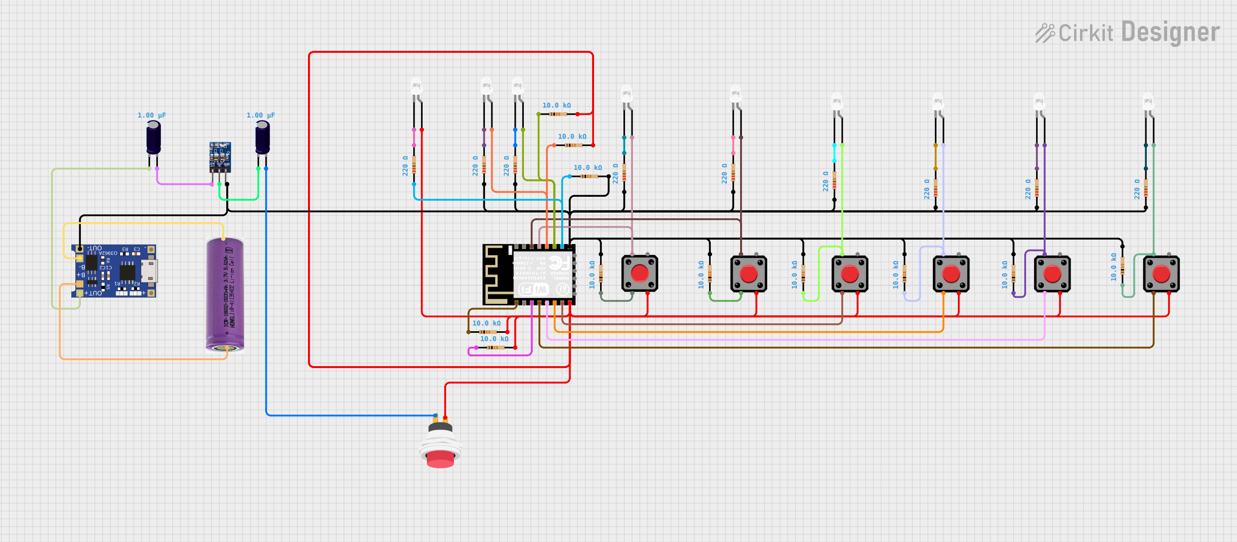
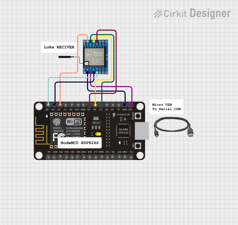
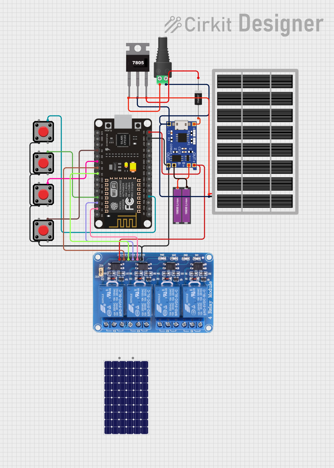
Explore Projects Built with ESp8266
Common Applications and Use Cases
- Home automation systems
- Smart appliances
- Wireless sensor networks
- IoT prototyping and development
- Remote monitoring and control systems
- Wi-Fi-enabled robotics
Technical Specifications
The ESP8266 is a highly integrated chip with the following key specifications:
| Parameter | Value |
|---|---|
| Manufacturer | Espressif Systems |
| Part ID | ESP8266 |
| Operating Voltage | 3.0V - 3.6V |
| Flash Memory | 512 KB to 4 MB (varies by module) |
| RAM | 64 KB instruction RAM, 96 KB data RAM |
| Wi-Fi Standards | 802.11 b/g/n |
| Frequency Range | 2.4 GHz |
| GPIO Pins | Up to 17 (varies by module) |
| Communication Interfaces | UART, SPI, I2C, I2S, PWM |
| CPU | Tensilica L106 32-bit RISC processor, clocked at 80 MHz (up to 160 MHz) |
| Power Consumption | 15 µA (deep sleep), 20 mA (idle), 200 mA (transmit peak) |
| Operating Temperature | -40°C to +125°C |
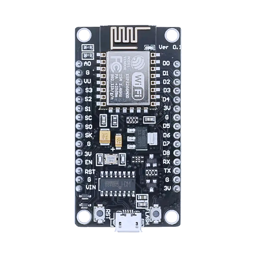
Pin Configuration and Descriptions
The ESP8266 is available in various module formats, such as ESP-01, ESP-12E, and NodeMCU. Below is the pin configuration for the ESP-12E module, one of the most commonly used variants:
| Pin | Name | Description |
|---|---|---|
| 1 | GND | Ground pin |
| 2 | GPIO0 | General-purpose I/O pin; used for boot mode selection during startup |
| 3 | GPIO2 | General-purpose I/O pin |
| 4 | GPIO4 | General-purpose I/O pin |
| 5 | GPIO5 | General-purpose I/O pin |
| 6 | RXD | UART receive pin |
| 7 | TXD | UART transmit pin |
| 8 | CH_PD | Chip enable pin; must be pulled high for normal operation |
| 9 | VCC | Power supply input (3.3V) |
| 10 | RST | Reset pin; active low |
| 11 | GPIO12 | General-purpose I/O pin |
| 12 | GPIO13 | General-purpose I/O pin |
| 13 | GPIO14 | General-purpose I/O pin |
| 14 | GPIO15 | General-purpose I/O pin; must be pulled low for booting |
| 15 | GPIO16 | General-purpose I/O pin; can also be used for deep sleep wake-up |
| 16 | ADC (A0) | Analog-to-digital converter input (10-bit resolution) |
Usage Instructions
The ESP8266 can be used in a variety of configurations, either as a standalone microcontroller or as a Wi-Fi module for other microcontrollers like the Arduino UNO. Below are the steps to use the ESP8266 in a circuit:
Standalone Mode
- Power Supply: Provide a stable 3.3V power supply to the VCC pin. Do not exceed 3.6V, as the ESP8266 is not 5V tolerant.
- Boot Mode Selection: Pull GPIO0 high for normal operation or low for firmware flashing.
- Connect Peripherals: Use the GPIO pins to connect sensors, actuators, or other peripherals.
- Programming: Use the UART interface (RXD and TXD pins) to upload code via a USB-to-serial adapter.
Arduino UNO Integration
- Voltage Level Shifting: Use a voltage divider or level shifter to interface the 5V Arduino UNO with the 3.3V ESP8266.
- Connections:
- Connect the Arduino's TX pin to the ESP8266's RXD pin (via a level shifter).
- Connect the Arduino's RX pin to the ESP8266's TXD pin.
- Connect the ESP8266's VCC and GND pins to a 3.3V power source and ground, respectively.
- Programming: Use the Arduino IDE to send AT commands or upload custom firmware.
Example Code for Arduino UNO
Below is an example of using the ESP8266 with an Arduino UNO to connect to a Wi-Fi network:
#include <SoftwareSerial.h>

// Define RX and TX pins for SoftwareSerial
SoftwareSerial esp8266(2, 3); // RX = Pin 2, TX = Pin 3

void setup() {
  Serial.begin(9600); // Start Serial Monitor
  esp8266.begin(9600); // Start ESP8266 communication

  // Send AT command to test communication
  esp8266.println("AT");
  delay(1000);

  // Connect to Wi-Fi network
  esp8266.println("AT+CWJAP=\"YourSSID\",\"YourPassword\"");
  delay(5000);

  // Check connection status
  esp8266.println("AT+CIFSR");
}

void loop() {
  // Forward data from ESP8266 to Serial Monitor
  if (esp8266.available()) {
    Serial.write(esp8266.read());
  }

  // Forward data from Serial Monitor to ESP8266
  if (Serial.available()) {
    esp8266.write(Serial.read());
  }
}
Important Considerations and Best Practices
- Always use a 3.3V power supply for the ESP8266. Exceeding this voltage can damage the chip.
- Use a capacitor (e.g., 10 µF) across the VCC and GND pins to stabilize the power supply.
- Avoid leaving unused GPIO pins floating; pull them high or low as needed.
- For firmware updates, ensure GPIO0 is pulled low during startup.
Troubleshooting and FAQs
Common Issues
ESP8266 Not Responding to AT Commands
- Solution: Check the baud rate. The default baud rate for some modules is 115200. Adjust your serial monitor and code accordingly.
- Solution: Ensure the ESP8266 is powered correctly and the CH_PD pin is pulled high.
Wi-Fi Connection Fails
- Solution: Double-check the SSID and password in your code.
- Solution: Ensure the Wi-Fi network is within range and supports 2.4 GHz (not 5 GHz).
Module Overheating
- Solution: Verify that the power supply is stable and does not exceed 3.6V.
- Solution: Add a heat sink or improve ventilation if the module is used in a high-temperature environment.
Random Resets or Instability
- Solution: Use a capacitor across the power supply pins to filter noise.
- Solution: Check for proper grounding and avoid long wires for power connections.
FAQs
Can the ESP8266 be programmed using the Arduino IDE?
- Yes, the ESP8266 can be programmed directly using the Arduino IDE by installing the ESP8266 board package.
What is the maximum range of the ESP8266?
- The ESP8266 has a range of approximately 100 meters in open space, but this may vary depending on environmental factors.
Can the ESP8266 operate on a 5V power supply?
- No, the ESP8266 is not 5V tolerant. Always use a 3.3V power supply.
How do I reset the ESP8266?
- Pull the RST pin low momentarily to reset the module.
By following this documentation, users can effectively integrate the ESP8266 into their projects and troubleshoot common issues.