Cirkit Designer Logo
Cirkit Designer
Your all-in-one circuit design IDE
Home / 
Component Documentation

How to Use Ambient Light Sensor: Examples, Pinouts, and Specs

Image of Ambient Light Sensor
Cirkit Designer LogoDesign with Ambient Light Sensor in Cirkit Designer

Introduction

An ambient light sensor (ALS) is an electronic component that measures the intensity of light in its environment and provides a corresponding output, typically in the form of an analog or digital signal. These sensors are widely used in applications such as adjusting the brightness of screens on mobile devices, controlling the lighting in smart homes, and in automotive systems to control headlight brightness.

Explore Projects Built with Ambient Light Sensor

Use Cirkit Designer to design, explore, and prototype these projects online. Some projects support real-time simulation. Click "Open Project" to start designing instantly!
Arduino Nano Controlled Ambient Light Sensing and NeoPixel Display
Image of GuesturLED: A project utilizing Ambient Light Sensor in a practical application
This circuit features an Arduino Nano microcontroller interfaced with an APDS-9930 Proximity and Ambient Light Sensor for sensing environmental light and proximity. The Arduino Nano also controls an Adafruit Quarter 60 NeoPixel Ring, likely for visual feedback or display purposes. The sensor communicates with the Arduino via I2C (SDA and SCL connections), and the NeoPixel Ring is driven by a digital output (D8) from the Arduino.
Cirkit Designer LogoOpen Project in Cirkit Designer
ESP32-Based Ambient Light Sensing System
Image of color sensor interfacing: A project utilizing Ambient Light Sensor in a practical application
This circuit integrates an ESP32 Wroom microcontroller with an APDS-9930 Proximity and Ambient Light Sensor. The ESP32 provides power to the sensor and communicates with it via I2C, using its GPIO21/SDA and GPIO22/SCL pins for data transfer. The circuit is designed to measure proximity and ambient light levels, which can be processed and utilized by the ESP32 for various applications.
Cirkit Designer LogoOpen Project in Cirkit Designer
Raspberry Pi 5 Ambient Light Sensor System
Image of light sensor: A project utilizing Ambient Light Sensor in a practical application
This circuit connects a Raspberry Pi 5 to an ambient light sensor. The Raspberry Pi provides power and ground to the sensor, and communicates with it using I2C protocol through GPIO pins 2 (SDA) and 3 (SCL), with an interrupt line connected to GPIO pin 4.
Cirkit Designer LogoOpen Project in Cirkit Designer
Arduino UNO Proximity and Ambient Light Sensor with APDS-9930
Image of APDS-9930 sensor: A project utilizing Ambient Light Sensor in a practical application
This circuit interfaces an Arduino UNO with an APDS-9930 Proximity and Ambient Light Sensor. The Arduino reads proximity data from the sensor via I2C communication and prints the values to the Serial Monitor.
Cirkit Designer LogoOpen Project in Cirkit Designer

Explore Projects Built with Ambient Light Sensor

Use Cirkit Designer to design, explore, and prototype these projects online. Some projects support real-time simulation. Click "Open Project" to start designing instantly!
Image of GuesturLED: A project utilizing Ambient Light Sensor in a practical application
Arduino Nano Controlled Ambient Light Sensing and NeoPixel Display
This circuit features an Arduino Nano microcontroller interfaced with an APDS-9930 Proximity and Ambient Light Sensor for sensing environmental light and proximity. The Arduino Nano also controls an Adafruit Quarter 60 NeoPixel Ring, likely for visual feedback or display purposes. The sensor communicates with the Arduino via I2C (SDA and SCL connections), and the NeoPixel Ring is driven by a digital output (D8) from the Arduino.
Cirkit Designer LogoOpen Project in Cirkit Designer
Image of color sensor interfacing: A project utilizing Ambient Light Sensor in a practical application
ESP32-Based Ambient Light Sensing System
This circuit integrates an ESP32 Wroom microcontroller with an APDS-9930 Proximity and Ambient Light Sensor. The ESP32 provides power to the sensor and communicates with it via I2C, using its GPIO21/SDA and GPIO22/SCL pins for data transfer. The circuit is designed to measure proximity and ambient light levels, which can be processed and utilized by the ESP32 for various applications.
Cirkit Designer LogoOpen Project in Cirkit Designer
Image of light sensor: A project utilizing Ambient Light Sensor in a practical application
Raspberry Pi 5 Ambient Light Sensor System
This circuit connects a Raspberry Pi 5 to an ambient light sensor. The Raspberry Pi provides power and ground to the sensor, and communicates with it using I2C protocol through GPIO pins 2 (SDA) and 3 (SCL), with an interrupt line connected to GPIO pin 4.
Cirkit Designer LogoOpen Project in Cirkit Designer
Image of APDS-9930 sensor: A project utilizing Ambient Light Sensor in a practical application
Arduino UNO Proximity and Ambient Light Sensor with APDS-9930
This circuit interfaces an Arduino UNO with an APDS-9930 Proximity and Ambient Light Sensor. The Arduino reads proximity data from the sensor via I2C communication and prints the values to the Serial Monitor.
Cirkit Designer LogoOpen Project in Cirkit Designer

Technical Specifications

Key Technical Details

  • Supply Voltage (Vdd): 2.5V to 3.6V
  • Operating Current: 200µA (typical)
  • Output Type: Analog voltage or Digital (I2C, PWM)
  • Spectral Response: Similar to the human eye (400nm to 700nm)
  • Ambient Light Detection Range: 1 lux to 65535 lux
  • Temperature Range: -40°C to +85°C

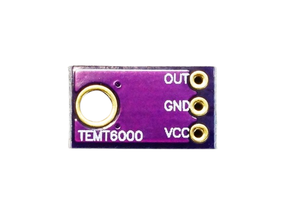
Pin Configuration and Descriptions

Pin Number Name Description
1 VDD Power supply voltage (2.5V to 3.6V)
2 GND Ground connection
3 SDA I2C Data (for digital output models)
4 SCL I2C Clock (for digital output models)
5 OUT Analog voltage output (for analog models)
6 ADDR I2C Address select (for digital output models)

Usage Instructions

Integration into a Circuit

  1. Power Supply: Connect the VDD pin to a power source within the specified voltage range and the GND pin to the ground of your circuit.
  2. Output Connection:
    • For analog models, connect the OUT pin to an analog input on your microcontroller.
    • For digital models, connect the SDA and SCL pins to the corresponding I2C pins on your microcontroller.
  3. Address Selection (Digital Models): If applicable, set the ADDR pin to the correct logic level to determine the sensor's I2C address.

Best Practices

  • Avoid Direct Sunlight: To prevent saturation, do not expose the sensor to direct sunlight.
  • Bypass Capacitor: Place a 0.1µF capacitor close to the VDD pin to filter out power supply noise.
  • Calibration: Calibrate the sensor for the specific application and lighting conditions for accurate readings.
  • I2C Pull-up Resistors: Ensure that appropriate pull-up resistors are used on the SDA and SCL lines for I2C communication.

Example Code for Arduino UNO

#include <Wire.h>

// Define the I2C address for the sensor (if applicable)
#define ALS_I2C_ADDRESS 0x39

void setup() {
  Wire.begin(); // Initialize I2C
  Serial.begin(9600); // Start serial communication at 9600 baud
  // Configure the ambient light sensor here if necessary
}

void loop() {
  Wire.beginTransmission(ALS_I2C_ADDRESS);
  // Request a reading from the sensor
  Wire.requestFrom(ALS_I2C_ADDRESS, 2); // Request 2 bytes for the light level
  if (Wire.available() == 2) {
    int lightLevel = Wire.read(); // Read the first byte
    lightLevel |= Wire.read() << 8; // Read the second byte and combine
    Serial.print("Ambient Light Level: ");
    Serial.println(lightLevel);
  }
  Wire.endTransmission();
  
  delay(1000); // Wait for 1 second before the next reading
}

Troubleshooting and FAQs

Common Issues

  • No Output Signal: Ensure that the sensor is correctly powered and that the pins are properly connected.
  • Inaccurate Readings: Check for any sources of light interference and calibrate the sensor accordingly.
  • I2C Communication Errors: Verify the pull-up resistors on the SDA and SCL lines and check for correct I2C address.

Solutions and Tips

  • Power Supply Issues: Use a stable power supply and check the voltage levels at the VDD pin.
  • Light Interference: Shield the sensor from ambient light not relevant to the application.
  • I2C Troubleshooting: Use an I2C scanner sketch to confirm the sensor's address and connectivity.

FAQs

Q: Can the sensor be used outdoors? A: Yes, but it should be shielded from direct sunlight and extreme weather conditions.

Q: How do I change the I2C address? A: The I2C address can be changed by connecting the ADDR pin to either VDD or GND, depending on the sensor's datasheet.

Q: What is the sensor's response time? A: The response time varies by model. Refer to the specific sensor's datasheet for this information.

Q: Can the sensor detect colored light? A: The sensor has a spectral response similar to the human eye and can detect a wide range of light, but it does not differentiate between colors.