
How to Use Motortreiber: Examples, Pinouts, and Specs
 Design with Motortreiber in Cirkit Designer
Introduction
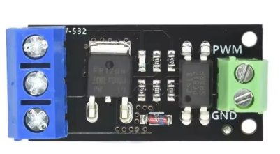
The Motortreiber (Motor Driver) is an electronic circuit designed to control the operation of motors by providing the necessary voltage and current. Manufactured by Gerui, this motor driver (Part ID: LR7843 FR120N D4184) enables precise control of motor speed and direction, making it an essential component in robotics, automation, and other motor-driven applications.
Explore Projects Built with Motortreiber
 Open Project in Cirkit Designer
 Open Project in Cirkit Designer
 Open Project in Cirkit Designer
 Open Project in Cirkit Designer
Explore Projects Built with Motortreiber
Open Project in Cirkit DesignerOpen Project in Cirkit DesignerOpen Project in Cirkit DesignerOpen Project in Cirkit DesignerCommon Applications
- Robotics: Controlling DC motors for movement and steering.
- Automation: Driving conveyor belts, robotic arms, and other automated systems.
- Remote-Controlled Vehicles: Managing motor speed and direction for wheels or propellers.
- Industrial Equipment: Operating motors in manufacturing and assembly lines.
Technical Specifications
Key Technical Details
| Parameter | Value |
|---|---|
| Manufacturer | Gerui |
| Part ID | LR7843 FR120N D4184 |
| Operating Voltage Range | 5V to 36V |
| Maximum Current | 15A (continuous), 30A (peak) |
| Control Logic Voltage | 3.3V to 5V |
| Motor Channels | 2 (dual-channel) |
| PWM Frequency | Up to 20 kHz |
| Operating Temperature | -40°C to 85°C |
Pin Configuration and Descriptions
The Motortreiber has the following pin configuration:
Input Pins
| Pin Name | Description |
|---|---|
| IN1 | Input signal for controlling Motor 1 (PWM) |
| IN2 | Input signal for controlling Motor 1 (Direction) |
| IN3 | Input signal for controlling Motor 2 (PWM) |
| IN4 | Input signal for controlling Motor 2 (Direction) |
| ENA | Enable pin for Motor 1 |
| ENB | Enable pin for Motor 2 |
Output Pins
| Pin Name | Description |
|---|---|
| OUT1 | Output to Motor 1 terminal A |
| OUT2 | Output to Motor 1 terminal B |
| OUT3 | Output to Motor 2 terminal A |
| OUT4 | Output to Motor 2 terminal B |
Power Pins
| Pin Name | Description |
|---|---|
| VCC | Power supply for the motor driver (5V-36V) |
| GND | Ground connection |
Usage Instructions
How to Use the Motortreiber in a Circuit
- Power Supply: Connect the VCC pin to a power source (5V-36V) and the GND pin to ground.
- Motor Connections: Attach the motor terminals to the corresponding output pins (OUT1/OUT2 for Motor 1, OUT3/OUT4 for Motor 2).
- Control Signals: Use a microcontroller (e.g., Arduino UNO) to send PWM signals to the input pins (IN1, IN2, IN3, IN4) for speed and direction control.
- Enable Pins: Ensure the ENA and ENB pins are set HIGH to enable the motors.
Important Considerations
- Heat Dissipation: The driver may heat up during operation. Use a heat sink or cooling fan for high-current applications.
- Voltage Matching: Ensure the motor voltage matches the power supply voltage to avoid damage.
- Current Limiting: Do not exceed the maximum current rating (15A continuous, 30A peak).
Example Code for Arduino UNO
Below is an example of how to control two motors using the Motortreiber with an Arduino UNO:
// Define motor control pins
const int ENA = 9;  // Enable pin for Motor 1
const int ENB = 10; // Enable pin for Motor 2
const int IN1 = 2;  // Direction pin for Motor 1
const int IN2 = 3;  // PWM pin for Motor 1
const int IN3 = 4;  // Direction pin for Motor 2
const int IN4 = 5;  // PWM pin for Motor 2

void setup() {
  // Set motor control pins as outputs
  pinMode(ENA, OUTPUT);
  pinMode(ENB, OUTPUT);
  pinMode(IN1, OUTPUT);
  pinMode(IN2, OUTPUT);
  pinMode(IN3, OUTPUT);
  pinMode(IN4, OUTPUT);

  // Enable both motors
  digitalWrite(ENA, HIGH);
  digitalWrite(ENB, HIGH);
}

void loop() {
  // Motor 1: Forward at 50% speed
  digitalWrite(IN1, HIGH);  // Set direction
  analogWrite(IN2, 128);    // Set speed (0-255)

  // Motor 2: Reverse at 75% speed
  digitalWrite(IN3, LOW);   // Set direction
  analogWrite(IN4, 192);    // Set speed (0-255)

  delay(2000); // Run motors for 2 seconds

  // Stop both motors
  analogWrite(IN2, 0);
  analogWrite(IN4, 0);

  delay(2000); // Pause for 2 seconds
}
Troubleshooting and FAQs
Common Issues
Motors Not Running:
- Ensure the ENA and ENB pins are set HIGH.
- Verify the power supply voltage and current are sufficient for the motors.
- Check the wiring for loose or incorrect connections.
Overheating:
- Use a heat sink or cooling fan if the driver becomes too hot.
- Reduce the motor load or operating current.
Erratic Motor Behavior:
- Ensure the PWM signals are within the supported frequency range (up to 20 kHz).
- Check for noise or interference in the control signals.
FAQs
Can I use this driver with stepper motors?
- No, this driver is designed for DC motors. Use a dedicated stepper motor driver for stepper motors.
What happens if I exceed the maximum current rating?
- Exceeding the current rating may damage the driver. Use current-limiting resistors or a fuse for protection.
Can I control the driver with a 3.3V microcontroller?
- Yes, the control logic voltage range is 3.3V to 5V, making it compatible with 3.3V microcontrollers like the ESP32.
By following this documentation, you can effectively integrate the Gerui Motortreiber (LR7843 FR120N D4184) into your projects for reliable motor control.