How to Use 433 MHz RF Receiver Module: Examples, Pinouts, and Specs
Introduction
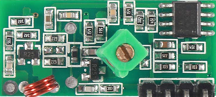
The 433 MHz RF Receiver Module is a compact and cost-effective device designed to receive radio frequency (RF) signals at a frequency of 433 MHz. It is widely used in wireless communication systems for applications such as remote controls, home automation, wireless sensors, and data transmission. This module is ideal for projects requiring low-power, short-range communication.
Common applications include:
- Wireless remote controls (e.g., garage doors, lighting systems)
- Home automation systems
- Wireless sensor networks
- Internet of Things (IoT) devices
- Data transmission between microcontrollers
Explore Projects Built with 433 MHz RF Receiver Module


Explore Projects Built with 433 MHz RF Receiver Module
Technical Specifications
The 433 MHz RF Receiver Module is designed to work seamlessly with a corresponding 433 MHz RF transmitter. Below are the key technical details and pin configuration:
Key Technical Details
| Parameter | Specification |
|---|---|
| Operating Voltage | 5V DC |
| Operating Current | 4 mA (typical) |
| Operating Frequency | 433 MHz |
| Sensitivity | -105 dBm |
| Data Rate | Up to 10 kbps |
| Range | Up to 50-100 meters (line of sight) |
| Modulation Type | Amplitude Shift Keying (ASK) |
| Dimensions | ~30mm x 14mm x 7mm |
Pin Configuration and Descriptions
| Pin Number | Pin Name | Description |
|---|---|---|
| 1 | GND | Ground connection |
| 2 | DATA | Data output pin |
| 3 | VCC | Power supply (5V DC) |
| 4 | ANT | Antenna connection for signal input |
Usage Instructions
How to Use the 433 MHz RF Receiver Module in a Circuit
- Power the Module: Connect the
VCCpin to a 5V DC power source and theGNDpin to ground. - Connect the Data Pin: The
DATApin outputs the received signal. Connect this pin to a microcontroller (e.g., Arduino) or a decoder IC to process the received data. - Attach an Antenna: For optimal performance, connect a 17 cm wire to the
ANTpin to act as an antenna. Ensure the antenna is straight and positioned away from interference sources. - Pair with a Transmitter: Use a compatible 433 MHz RF transmitter module to send data to the receiver.
Important Considerations and Best Practices
- Power Supply: Ensure a stable 5V power supply to avoid noise and signal distortion.
- Antenna Placement: Position the antenna in an open area, away from metal objects or other RF sources, to maximize range and signal quality.
- Data Decoding: The module outputs raw data, which may require additional processing or decoding using a microcontroller or dedicated IC.
- Interference: Avoid using the module in environments with heavy RF interference, as this can degrade performance.
Example: Connecting to an Arduino UNO
Below is an example of how to use the 433 MHz RF Receiver Module with an Arduino UNO to receive data:
Circuit Connections
- Connect the
VCCpin of the module to the 5V pin on the Arduino. - Connect the
GNDpin of the module to the GND pin on the Arduino. - Connect the
DATApin of the module to digital pin 2 on the Arduino.
Arduino Code
// Include the RadioHead library for RF communication
#include <RH_ASK.h>
#include <SPI.h> // Required for RadioHead library

// Initialize the RF receiver object
RH_ASK rf_driver;

void setup() {
  Serial.begin(9600); // Initialize serial communication
  if (!rf_driver.init()) {
    Serial.println("RF Receiver initialization failed!");
    while (1); // Halt execution if initialization fails
  }
  Serial.println("RF Receiver initialized successfully.");
}

void loop() {
  uint8_t buf[RH_ASK_MAX_MESSAGE_LEN]; // Buffer to store received data
  uint8_t buflen = sizeof(buf);        // Length of the buffer

  // Check if data is available and read it
  if (rf_driver.recv(buf, &buflen)) {
    Serial.print("Received: ");
    for (int i = 0; i < buflen; i++) {
      Serial.print((char)buf[i]); // Print received data as characters
    }
    Serial.println();
  }
}
Notes:
- Install the RadioHead library in the Arduino IDE before uploading the code. You can find it in the Library Manager.
- Ensure the transmitter module is sending data at the same frequency and modulation type.
Troubleshooting and FAQs
Common Issues and Solutions
No Data Received
- Ensure the transmitter and receiver are operating at the same frequency (433 MHz).
- Check the antenna connection and placement for both modules.
- Verify that the
DATApin is correctly connected to the microcontroller.
Short Range
- Use a longer, straight antenna (17 cm is optimal for 433 MHz).
- Minimize obstacles and interference between the transmitter and receiver.
Noise or Corrupted Data
- Use a stable power supply to reduce noise.
- Implement error-checking algorithms in your code to filter out invalid data.
Module Not Powering On
- Verify the power supply voltage is 5V.
- Check for loose or incorrect connections.
FAQs
Q: Can I use this module with a 3.3V microcontroller?
A: The module requires a 5V power supply, but the DATA pin output is typically compatible with 3.3V logic. Use a level shifter if needed for safe operation.
Q: What is the maximum range of this module?
A: The range is typically 50-100 meters in open space. Obstacles and interference can reduce the range.
Q: Can I use multiple receiver modules in the same area?
A: Yes, but ensure that only one transmitter is active at a time to avoid signal collisions.
Q: How do I improve signal reliability?
A: Use a proper antenna, minimize interference, and implement error-checking in your code.
This documentation provides a comprehensive guide to using the 433 MHz RF Receiver Module effectively in your projects.