
How to Use Thumbstick: Examples, Pinouts, and Specs
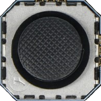
 Design with Thumbstick in Cirkit Designer
Introduction
A thumbstick is a control device that allows for directional input, commonly used in gaming controllers and joysticks. It consists of a stick that pivots on a base, enabling the user to manipulate movement in multiple directions. Thumbsticks are typically used in applications requiring precise control, such as gaming, robotics, and remote-controlled devices. They are also popular in DIY electronics projects for creating user interfaces or controlling motors and servos.
Explore Projects Built with Thumbstick
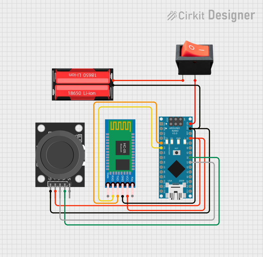 Open Project in Cirkit Designer
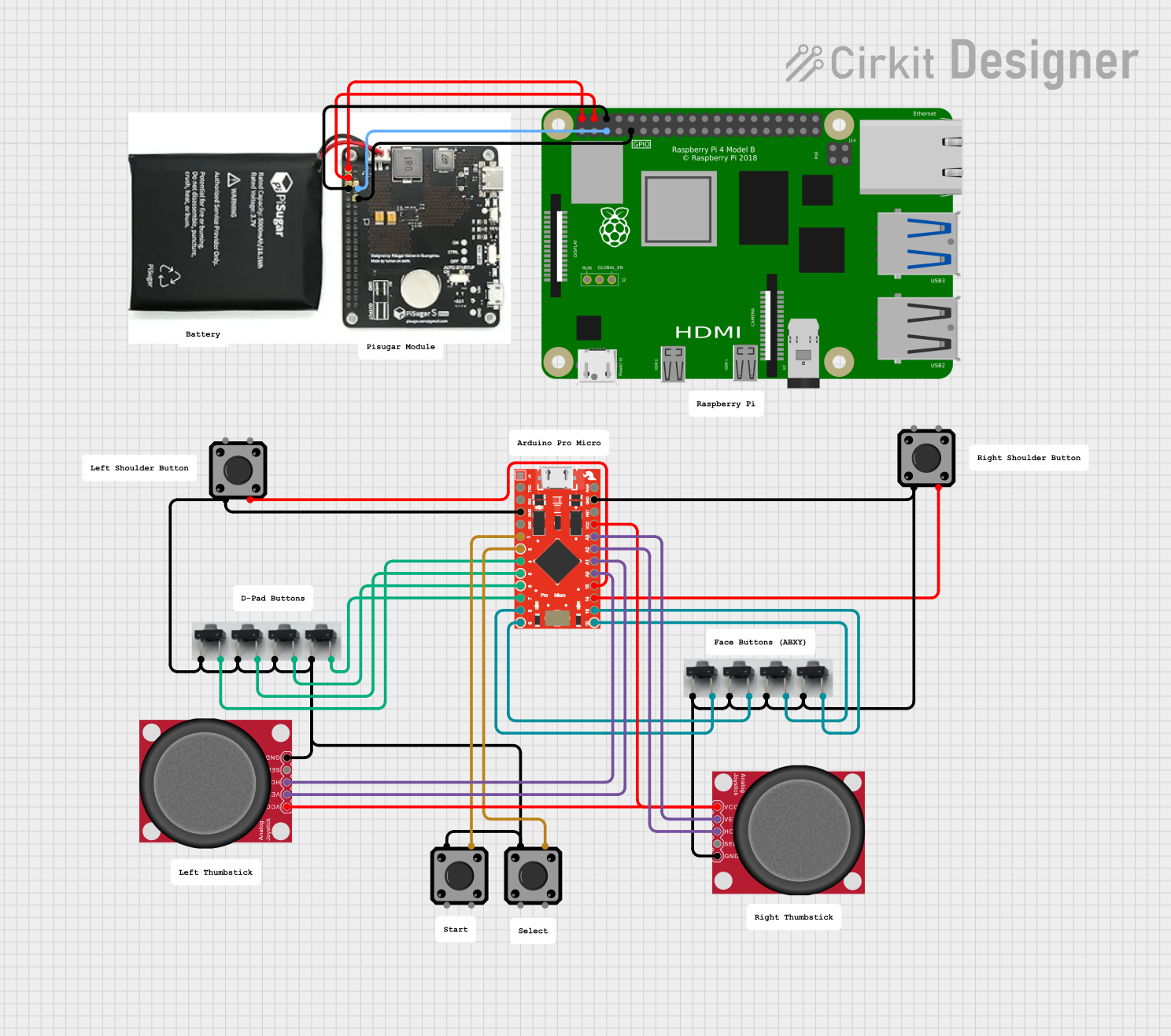 Open Project in Cirkit Designer
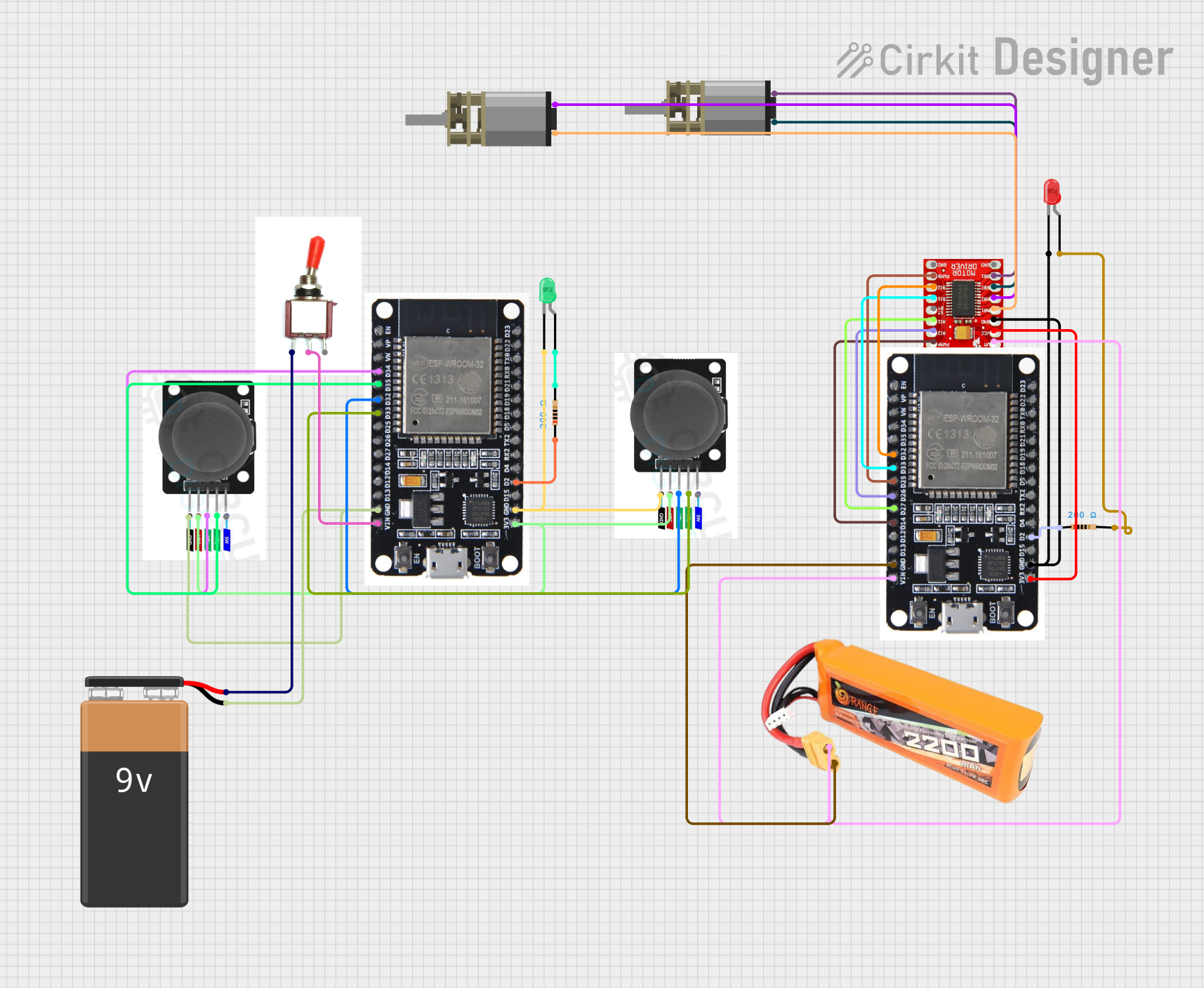 Open Project in Cirkit Designer
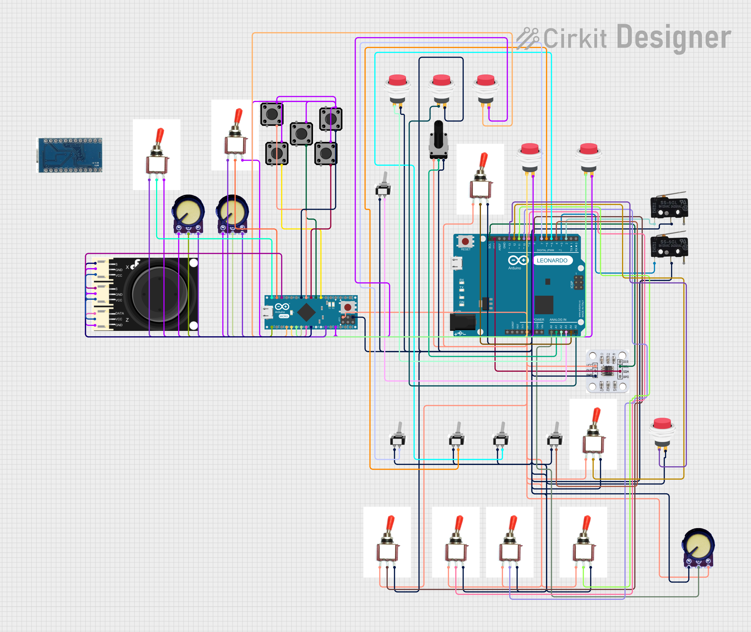 Open Project in Cirkit Designer
Explore Projects Built with Thumbstick
Open Project in Cirkit DesignerOpen Project in Cirkit DesignerOpen Project in Cirkit DesignerOpen Project in Cirkit DesignerTechnical Specifications
- Type: Analog joystick module
- Operating Voltage: 3.3V to 5V
- Output: Two analog signals (X-axis and Y-axis) and one digital signal (button press)
- Dimensions: Approximately 34mm x 26mm x 32mm
- Interface: 5 pins (VCC, GND, VRx, VRy, SW)
- Movement Range: 360° (2D directional control)
- Button Type: Momentary push-button (activated by pressing the stick)
Pin Configuration and Descriptions
| Pin Name | Type | Description |
|---|---|---|
| VCC | Power | Connect to the positive voltage supply (3.3V or 5V). |
| GND | Ground | Connect to the ground of the circuit. |
| VRx | Analog Out | Outputs the X-axis position as an analog voltage (0V to VCC). |
| VRy | Analog Out | Outputs the Y-axis position as an analog voltage (0V to VCC). |
| SW | Digital Out | Outputs a digital signal (LOW when the stick is pressed, HIGH otherwise). |
Usage Instructions
How to Use the Thumbstick in a Circuit
Connect the Pins:
- Connect the
VCCpin to a 3.3V or 5V power supply. - Connect the
GNDpin to the ground of your circuit. - Connect the
VRxandVRypins to the analog input pins of your microcontroller (e.g., Arduino). - Connect the
SWpin to a digital input pin of your microcontroller.
- Connect the
Read the Outputs:
- The
VRxandVRypins provide analog voltage outputs corresponding to the stick's position along the X and Y axes. - The
SWpin provides a digital signal that indicates whether the stick is pressed.
- The
Calibrate the Thumbstick:
- The analog outputs typically range from 0V to VCC, with the center position being approximately half of VCC.
- Use software to map the analog values to a usable range (e.g., -100 to 100 for directional control).
Example Code for Arduino UNO
The following code demonstrates how to read the thumbstick's X and Y positions and detect button presses using an Arduino UNO:
// Define pin connections for the thumbstick
const int VRxPin = A0; // X-axis analog output connected to A0
const int VRyPin = A1; // Y-axis analog output connected to A1
const int SWPin = 2;   // Button digital output connected to digital pin 2

void setup() {
  // Initialize serial communication for debugging
  Serial.begin(9600);

  // Configure the button pin as input with an internal pull-up resistor
  pinMode(SWPin, INPUT_PULLUP);
}

void loop() {
  // Read the X and Y axis analog values
  int xValue = analogRead(VRxPin); // Range: 0 to 1023
  int yValue = analogRead(VRyPin); // Range: 0 to 1023

  // Read the button state (LOW when pressed, HIGH otherwise)
  int buttonState = digitalRead(SWPin);

  // Print the values to the Serial Monitor
  Serial.print("X: ");
  Serial.print(xValue);
  Serial.print(" | Y: ");
  Serial.print(yValue);
  Serial.print(" | Button: ");
  Serial.println(buttonState == LOW ? "Pressed" : "Released");

  // Add a small delay to avoid overwhelming the Serial Monitor
  delay(100);
}
Important Considerations and Best Practices
- Power Supply: Ensure the thumbstick is powered with the correct voltage (3.3V or 5V) to avoid damage.
- Debouncing: If the button press signal is noisy, implement software debouncing to ensure reliable detection.
- Calibration: Account for slight variations in the center position of the stick by calibrating the analog readings in your code.
- Mechanical Stress: Avoid applying excessive force to the thumbstick to prevent mechanical damage.
Troubleshooting and FAQs
Common Issues and Solutions
No Output from VRx or VRy:
- Ensure the
VCCandGNDpins are properly connected. - Verify that the analog pins on the microcontroller are functioning correctly.
- Ensure the
Button Not Detected:
- Check the connection to the
SWpin. - Ensure the pin is configured as an input with a pull-up resistor (use
INPUT_PULLUPin Arduino).
- Check the connection to the
Inconsistent Analog Readings:
- Verify that the power supply voltage is stable.
- Add a small capacitor (e.g., 0.1µF) between
VCCandGNDto filter noise.
Stick Does Not Return to Center:
- This may indicate mechanical wear or damage. Replace the thumbstick if necessary.
FAQs
Q: Can I use the thumbstick with a Raspberry Pi?
A: Yes, the thumbstick can be used with a Raspberry Pi. Connect the analog outputs (VRx and VRy) to an external ADC (Analog-to-Digital Converter) since the Raspberry Pi lacks built-in analog input pins.
Q: What is the typical range of analog values for VRx and VRy?
A: The analog values typically range from 0 to 1023 on a 10-bit ADC (e.g., Arduino UNO). The center position is approximately 512.
Q: Can the thumbstick be used for 3D control?
A: No, the thumbstick provides 2D directional control (X and Y axes) and a button press. For 3D control, consider using a joystick with an additional Z-axis.