How to Use PUSH BUTTON - STOP: Examples, Pinouts, and Specs
Introduction
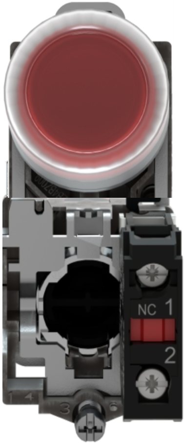
The Schneider XB4-BP42 is a high-quality, industrial-grade momentary push button designed to interrupt a circuit when pressed. It is commonly used as a "STOP" button in control panels, machinery, and safety systems. This push button is part of Schneider's XB4 series, known for its durability and reliability in demanding environments.
Explore Projects Built with PUSH BUTTON - STOP


Explore Projects Built with PUSH BUTTON - STOP
Common Applications
- Emergency stop mechanisms in industrial machinery
- Control panels for automation systems
- Safety circuits in manufacturing plants
- Operator interfaces in electronic devices
Technical Specifications
Key Technical Details
| Parameter | Value |
|---|---|
| Manufacturer | Schneider |
| Part Number | XB4-BP42 |
| Type | Momentary push button |
| Contact Configuration | 1 Normally Closed (1NC) |
| Rated Voltage | 24V to 240V AC/DC |
| Rated Current | 10A |
| Actuator Color | Red |
| Actuator Type | Flush |
| Mounting Diameter | 22mm |
| Mechanical Durability | 10 million operations |
| Operating Temperature | -25°C to +70°C |
| IP Rating | IP66, IP67, IP69, IP69K |
| Standards Compliance | IEC 60947-5-1, UL 508 |
Pin Configuration and Descriptions
The XB4-BP42 push button has a simple pin configuration, as shown below:
| Pin Label | Description |
|---|---|
| COM | Common terminal for the circuit |
| NC | Normally Closed terminal (opens when pressed) |
Usage Instructions
How to Use the Component in a Circuit
Mounting the Push Button:
- Drill a 22mm hole in the panel where the push button will be installed.
- Insert the push button into the hole and secure it using the mounting ring provided.
Wiring the Push Button:
- Connect the COM terminal to the power source or control circuit.
- Connect the NC terminal to the load or device you want to control.
- Ensure all connections are secure and insulated to prevent short circuits.
Testing the Circuit:
- Power on the circuit and press the push button.
- Verify that the circuit is interrupted (stops functioning) when the button is pressed.
- Release the button to restore the circuit.
Important Considerations and Best Practices
- Ensure the push button is rated for the voltage and current of your application.
- Use proper wire gauges and connectors to handle the electrical load safely.
- Avoid exposing the push button to extreme temperatures or corrosive environments beyond its rated specifications.
- Regularly inspect the push button for wear and tear, especially in high-use applications.
- For safety-critical applications, consider using redundancy or additional safety measures.
Example: Connecting to an Arduino UNO
The XB4-BP42 can be used with an Arduino UNO to detect button presses. Below is an example circuit and code:
Circuit Setup
- Connect the COM terminal of the push button to the Arduino's GND pin.
- Connect the NC terminal to a digital input pin (e.g., D2) on the Arduino.
- Use a pull-up resistor (10kΩ) between the digital input pin and 5V to ensure a stable signal.
Arduino Code
// Define the pin connected to the push button
const int buttonPin = 2;  // Digital pin 2 for the push button

// Variable to store the button state
int buttonState = 0;

void setup() {
  // Set the button pin as input with an internal pull-up resistor
  pinMode(buttonPin, INPUT_PULLUP);

  // Initialize serial communication for debugging
  Serial.begin(9600);
}

void loop() {
  // Read the state of the push button
  buttonState = digitalRead(buttonPin);

  // Check if the button is pressed (LOW state due to pull-up resistor)
  if (buttonState == LOW) {
    Serial.println("STOP button pressed!");
    // Add your stop logic here
  } else {
    Serial.println("STOP button released.");
  }

  // Small delay to debounce the button
  delay(50);
}
Troubleshooting and FAQs
Common Issues and Solutions
| Issue | Possible Cause | Solution |
|---|---|---|
| Button does not interrupt the circuit | Incorrect wiring | Verify connections to COM and NC pins. |
| Button feels stuck or unresponsive | Mechanical wear or debris | Clean the button or replace if damaged. |
| Circuit does not restore after release | Faulty wiring or damaged contacts | Inspect wiring and test continuity. |
| Arduino does not detect button press | Missing pull-up resistor or loose wires | Add a pull-up resistor and check wiring. |
FAQs
Can the XB4-BP42 be used outdoors?
Yes, the push button is rated IP66, IP67, IP69, and IP69K, making it suitable for outdoor and harsh environments.What is the difference between a momentary and latching push button?
A momentary push button (like the XB4-BP42) only changes the circuit state while pressed. A latching button maintains its state after being pressed.Can I use this push button for low-voltage applications?
Yes, the XB4-BP42 supports a wide voltage range from 24V to 240V AC/DC, making it suitable for low-voltage circuits.How do I clean the push button?
Use a soft, damp cloth to clean the button. Avoid using abrasive materials or solvents that could damage the surface.
By following this documentation, users can effectively integrate the Schneider XB4-BP42 push button into their projects and troubleshoot common issues with ease.