Cirkit Designer Logo
Cirkit Designer
Your all-in-one circuit design IDE
Home / 
Component Documentation

How to Use sx1509-breakout: Examples, Pinouts, and Specs

Image of sx1509-breakout
Cirkit Designer LogoDesign with sx1509-breakout in Cirkit Designer

Introduction

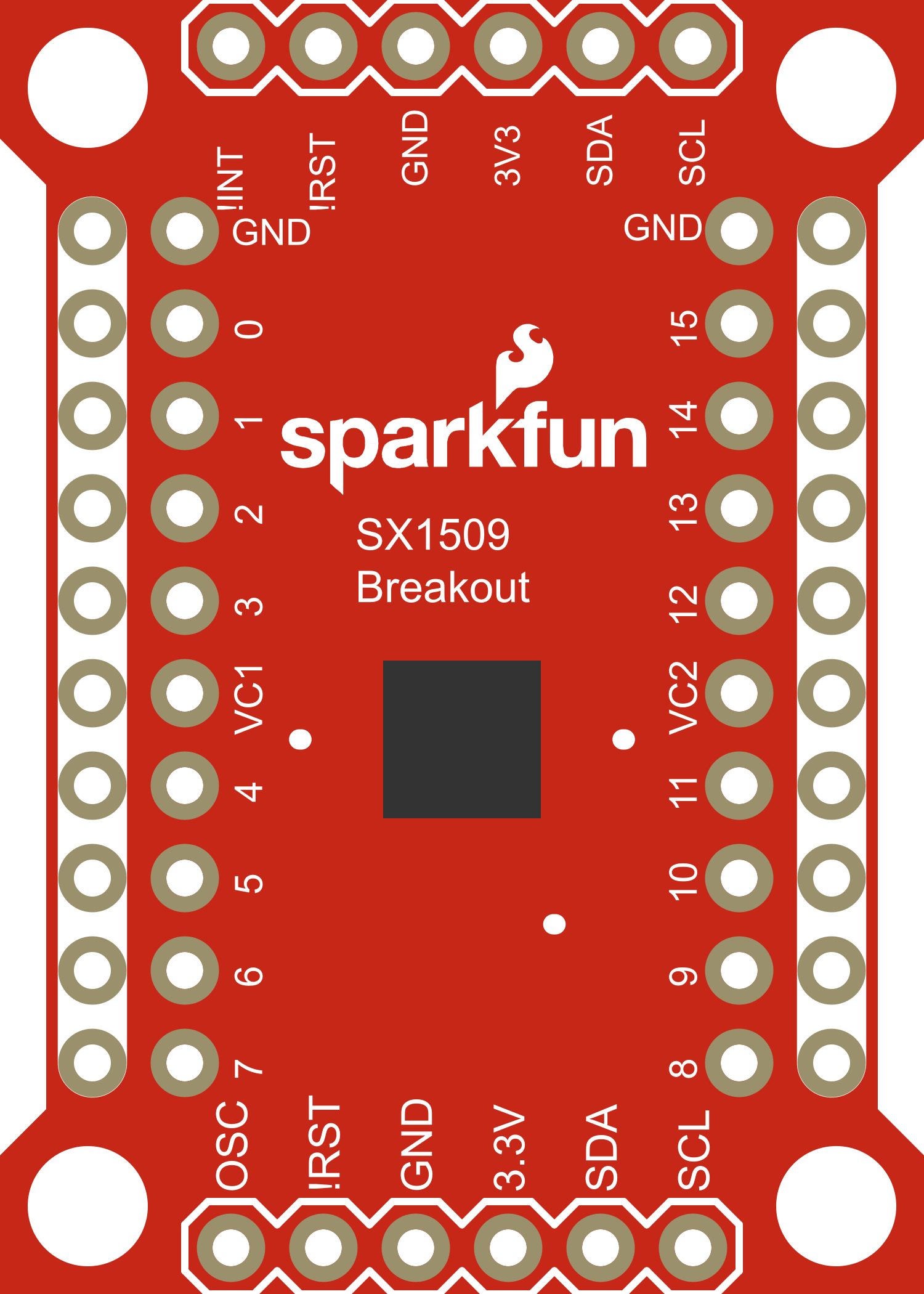
The SX1509 Breakout is a convenient solution for expanding the number of input/output (I/O) pins available on a microcontroller. Based on the Semtech SX1509 chip, this breakout board allows users to add 16 additional I/O pins through a simple I2C interface, which requires only two pins on the microcontroller. This component is particularly useful in projects where there is a need to control a large number of LEDs, buttons, or other digital devices, and it is commonly used with platforms like Arduino, Raspberry Pi, and others.

Explore Projects Built with sx1509-breakout

Use Cirkit Designer to design, explore, and prototype these projects online. Some projects support real-time simulation. Click "Open Project" to start designing instantly!
Raspberry Pi 3B Powered 15.6-inch Touchscreen Display with USB Type-C Power Delivery
Image of Pi Touch Screen Kiosk: A project utilizing sx1509-breakout in a practical application
This circuit powers a 15.6-inch capacitive touch display and a Raspberry Pi 3B using a USB Type C power delivery breakout and two buck converters. The Raspberry Pi connects to the display via HDMI and USB for touch functionality, while the power delivery breakout provides regulated power to both the display and the Raspberry Pi through the buck converters.
Cirkit Designer LogoOpen Project in Cirkit Designer
ESP32-CAM and IR Sensor Interface with USB UART Communication
Image of esp32cam parking: A project utilizing sx1509-breakout in a practical application
This circuit features an ESP32 CAM module interfaced with an IR sensor and a SparkFun USB UART Breakout board. The ESP32 CAM provides power to the IR sensor and receives its output signal, likely for processing or triggering camera actions based on IR detection. The USB UART Breakout board is connected to the ESP32 CAM for serial communication, enabling programming, debugging, or data exchange with a computer.
Cirkit Designer LogoOpen Project in Cirkit Designer
ESP32 CAM Wi-Fi Enabled Camera Module with USB Power
Image of abc: A project utilizing sx1509-breakout in a practical application
This circuit consists of an ESP32 CAM module powered by a Micro USB breakout board. The USB breakout board supplies 5V and ground to the ESP32 CAM, enabling it to function and perform tasks such as image capture and processing.
Cirkit Designer LogoOpen Project in Cirkit Designer
ESP32-Controlled Multi-Axis Actuator System with Orientation Sensing and Light Detection
Image of Auto_Level_Table: A project utilizing sx1509-breakout in a practical application
This circuit features an ESP32 S3 N32R8V microcontroller interfaced with multiple IBT-2 H-Bridge Motor Drivers to control several Linear Actuators, and it receives input from KY-018 LDR Photo Resistors and Pushbuttons. The ESP32 is powered by a 5V supply from an Adafruit MPM3610 5V Buck Converter, while the Linear Actuators and Motor Drivers are powered by a 12V 7Ah battery. Additionally, the ESP32 communicates with an Adafruit BNO085 9-DOF Orientation IMU Fusion Breakout for orientation sensing.
Cirkit Designer LogoOpen Project in Cirkit Designer

Explore Projects Built with sx1509-breakout

Use Cirkit Designer to design, explore, and prototype these projects online. Some projects support real-time simulation. Click "Open Project" to start designing instantly!
Image of Pi Touch Screen Kiosk: A project utilizing sx1509-breakout in a practical application
Raspberry Pi 3B Powered 15.6-inch Touchscreen Display with USB Type-C Power Delivery
This circuit powers a 15.6-inch capacitive touch display and a Raspberry Pi 3B using a USB Type C power delivery breakout and two buck converters. The Raspberry Pi connects to the display via HDMI and USB for touch functionality, while the power delivery breakout provides regulated power to both the display and the Raspberry Pi through the buck converters.
Cirkit Designer LogoOpen Project in Cirkit Designer
Image of esp32cam parking: A project utilizing sx1509-breakout in a practical application
ESP32-CAM and IR Sensor Interface with USB UART Communication
This circuit features an ESP32 CAM module interfaced with an IR sensor and a SparkFun USB UART Breakout board. The ESP32 CAM provides power to the IR sensor and receives its output signal, likely for processing or triggering camera actions based on IR detection. The USB UART Breakout board is connected to the ESP32 CAM for serial communication, enabling programming, debugging, or data exchange with a computer.
Cirkit Designer LogoOpen Project in Cirkit Designer
Image of abc: A project utilizing sx1509-breakout in a practical application
ESP32 CAM Wi-Fi Enabled Camera Module with USB Power
This circuit consists of an ESP32 CAM module powered by a Micro USB breakout board. The USB breakout board supplies 5V and ground to the ESP32 CAM, enabling it to function and perform tasks such as image capture and processing.
Cirkit Designer LogoOpen Project in Cirkit Designer
Image of Auto_Level_Table: A project utilizing sx1509-breakout in a practical application
ESP32-Controlled Multi-Axis Actuator System with Orientation Sensing and Light Detection
This circuit features an ESP32 S3 N32R8V microcontroller interfaced with multiple IBT-2 H-Bridge Motor Drivers to control several Linear Actuators, and it receives input from KY-018 LDR Photo Resistors and Pushbuttons. The ESP32 is powered by a 5V supply from an Adafruit MPM3610 5V Buck Converter, while the Linear Actuators and Motor Drivers are powered by a 12V 7Ah battery. Additionally, the ESP32 communicates with an Adafruit BNO085 9-DOF Orientation IMU Fusion Breakout for orientation sensing.
Cirkit Designer LogoOpen Project in Cirkit Designer

Common Applications and Use Cases

  • LED matrix control
  • Keypad input reading
  • Additional GPIOs for microcontrollers
  • Home automation
  • Robotics

Technical Specifications

Key Technical Details

  • Voltage: 1.2V to 3.6V
  • I2C Interface: 400kHz max
  • Output Current: Up to 15mA per channel
  • Internal Resistor: Pull-up and pull-down
  • PWM Outputs: 16 (8-bit resolution)
  • Input Debouncing
  • Interrupt Output

Pin Configuration and Descriptions

Pin Number Name Description
1 VCC Power supply (1.2V to 3.6V)
2 GND Ground connection
3 SDA I2C Data line
4 SCL I2C Clock line
5 INT Interrupt output (active low)
6-21 IO0-IO15 Bidirectional I/O pins

Usage Instructions

How to Use the Component in a Circuit

  1. Powering the SX1509: Connect the VCC pin to a power supply within the range of 1.2V to 3.6V and the GND pin to the ground.

  2. Connecting to a Microcontroller:

    • Connect the SDA pin to the I2C data line on your microcontroller.
    • Connect the SCL pin to the I2C clock line on your microcontroller.
    • If interrupt functionality is required, connect the INT pin to an interrupt-capable GPIO on your microcontroller.
  3. Address Selection: The SX1509 supports multiple I2C addresses. Set the address by connecting the ADDR pins according to the datasheet.

  4. Initialization: Initialize the SX1509 in your microcontroller's setup routine.

  5. Configuration: Configure the I/O pins as either inputs or outputs depending on your application.

Important Considerations and Best Practices

  • Ensure that the power supply voltage does not exceed the maximum rating of 3.6V.
  • Use pull-up resistors on the I2C lines if your microcontroller does not have them built-in.
  • Avoid drawing more than 15mA from any single I/O pin.
  • When using the interrupt feature, ensure that your microcontroller's interrupt pin is configured correctly.

Example Code for Arduino UNO

#include <Wire.h>
#include <SparkFunSX1509.h> // Include SX1509 library

// Create an SX1509 object
SX1509 io;

void setup() {
  Wire.begin(); // Start I2C
  if (!io.begin(0x3E)) { // Start SX1509 at I2C address 0x3E
    Serial.println("SX1509 not found. Please check wiring.");
    while (1);
  }

  // Configure pin 7 as an output
  io.pinMode(7, OUTPUT);
}

void loop() {
  // Blink LED on pin 7
  io.digitalWrite(7, HIGH); // Turn on LED
  delay(500);
  io.digitalWrite(7, LOW); // Turn off LED
  delay(500);
}

Troubleshooting and FAQs

Common Issues Users Might Face

  • I2C Communication Failure: Ensure that the SDA and SCL lines are connected properly and that there are pull-up resistors if needed.
  • Insufficient Power Supply: Verify that the power supply is within the specified voltage range and can provide enough current.
  • Non-Responsive I/O Pins: Check if the pins are configured correctly in your code as inputs or outputs.

Solutions and Tips for Troubleshooting

  • Use I2C scanner code to confirm that the SX1509 is detected on the I2C bus.
  • Check for soldering issues on the breakout board.
  • Ensure that the interrupt pin is not floating if used.

FAQs

Q: Can I use the SX1509 with a 5V microcontroller? A: Yes, but ensure that the SX1509's VCC is connected to a voltage within its range (1.2V to 3.6V), and use level shifters for the I2C lines if necessary.

Q: How many SX1509 boards can I chain together? A: You can chain multiple boards by setting unique I2C addresses for each SX1509 using the ADDR pins.

Q: Is it possible to use the PWM functionality on all pins? A: Yes, all 16 I/O pins of the SX1509 support 8-bit PWM output.