How to Use CD4510BE: Examples, Pinouts, and Specs
Introduction
The CD4510BE is a 4-bit binary coded decimal (BCD) counter IC manufactured by Texas Instruments. It is a versatile and reliable component designed for counting applications in digital systems. The IC can count in both up and down modes and features a carry-out signal for cascading multiple counters. It is commonly used in digital clocks, frequency counters, timers, and other applications requiring precise counting.
Explore Projects Built with CD4510BE


Explore Projects Built with CD4510BE
Common Applications and Use Cases
- Digital clocks and timers
- Frequency counters
- Event counters
- Digital displays
- Arithmetic operations in digital systems
Technical Specifications
Key Technical Details
| Parameter | Value |
|---|---|
| Supply Voltage (VDD) | 3V to 15V |
| Input Voltage Range | 0V to VDD |
| Maximum Clock Frequency | 6 MHz (at 10V supply) |
| Operating Temperature | -55°C to +125°C |
| Package Type | 16-pin Dual In-line Package (DIP) |
| Power Dissipation | 500 mW (maximum) |
Pin Configuration and Descriptions
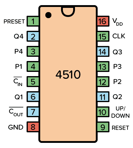
The CD4510BE has 16 pins, each with a specific function. The table below describes the pin configuration:
| Pin No. | Pin Name | Description |
|---|---|---|
| 1 | MR | Master Reset: Resets the counter to 0 when set HIGH. |
| 2 | CPD | Clock Pulse Down: Decrements the counter on the falling edge of the clock. |
| 3 | CPU | Clock Pulse Up: Increments the counter on the rising edge of the clock. |
| 4 | PE | Preset Enable: Loads the preset value when set HIGH. |
| 5 | Q1 | Output Bit 1 (Least Significant Bit). |
| 6 | Q2 | Output Bit 2. |
| 7 | Q3 | Output Bit 3. |
| 8 | VSS | Ground (0V). |
| 9 | Q4 | Output Bit 4 (Most Significant Bit). |
| 10 | TC | Terminal Count: Indicates when the counter reaches its maximum value. |
| 11 | P1 | Preset Input Bit 1. |
| 12 | P2 | Preset Input Bit 2. |
| 13 | P3 | Preset Input Bit 3. |
| 14 | P4 | Preset Input Bit 4. |
| 15 | VDD | Positive Supply Voltage. |
| 16 | CE | Count Enable: Enables counting when set HIGH. |
Usage Instructions
How to Use the CD4510BE in a Circuit
- Power Supply: Connect the VDD pin to a positive voltage source (3V to 15V) and the VSS pin to ground.
- Clock Input: Provide clock pulses to the CPU (for counting up) or CPD (for counting down) pins. Use only one clock input at a time.
- Preset Functionality: To load a specific value into the counter, set the desired value on the P1–P4 pins, enable the PE pin, and then disable it.
- Reset: To reset the counter to 0, set the MR pin HIGH momentarily.
- Output: The counter's current value is available on the Q1–Q4 pins, with Q1 being the least significant bit (LSB) and Q4 the most significant bit (MSB).
- Cascading Counters: Use the TC pin to cascade multiple CD4510BE ICs for higher counting ranges.
Important Considerations and Best Practices
- Ensure the clock signal is clean and free of noise to avoid counting errors.
- Use pull-down resistors on unused input pins to prevent floating states.
- Avoid exceeding the maximum voltage ratings to prevent damage to the IC.
- For cascading, connect the TC pin of the first counter to the clock input of the next counter.
Example: Connecting CD4510BE to an Arduino UNO
The CD4510BE can be interfaced with an Arduino UNO to control its counting operation. Below is an example code snippet:
// Define pin connections
const int clockPin = 3;  // Arduino pin connected to CPU or CPD
const int resetPin = 4;  // Arduino pin connected to MR
const int enablePin = 5; // Arduino pin connected to CE

void setup() {
  pinMode(clockPin, OUTPUT); // Set clock pin as output
  pinMode(resetPin, OUTPUT); // Set reset pin as output
  pinMode(enablePin, OUTPUT); // Set enable pin as output

  // Initialize pins
  digitalWrite(clockPin, LOW);
  digitalWrite(resetPin, LOW);
  digitalWrite(enablePin, HIGH); // Enable counting
}

void loop() {
  // Generate a clock pulse
  digitalWrite(clockPin, HIGH);
  delay(100); // Wait for 100ms
  digitalWrite(clockPin, LOW);
  delay(100); // Wait for 100ms

  // Example: Reset the counter every 10 seconds
  static unsigned long lastReset = 0;
  if (millis() - lastReset > 10000) {
    digitalWrite(resetPin, HIGH); // Trigger reset
    delay(10); // Hold reset for 10ms
    digitalWrite(resetPin, LOW); // Release reset
    lastReset = millis();
  }
}
Troubleshooting and FAQs
Common Issues and Solutions
Counter Not Incrementing or Decrementing:
- Ensure the clock signal is connected to the correct pin (CPU for up, CPD for down).
- Verify that the CE pin is set HIGH to enable counting.
Incorrect Output Values:
- Check the preset inputs (P1–P4) and ensure they are set correctly.
- Verify that the PE pin is LOW during normal counting operation.
Counter Resets Unexpectedly:
- Ensure the MR pin is not floating. Use a pull-down resistor if necessary.
- Check for noise or glitches on the MR pin.
Cascading Counters Not Working:
- Verify the TC pin of the first counter is connected to the clock input of the next counter.
- Ensure all counters share a common ground and power supply.
FAQs
Q1: Can the CD4510BE count in hexadecimal?
No, the CD4510BE is a BCD counter, meaning it counts in decimal (0–9) and resets after reaching 9.
Q2: What is the maximum counting speed?
The maximum clock frequency is 6 MHz when powered at 10V. Ensure the clock signal does not exceed this limit.
Q3: Can I use both CPU and CPD simultaneously?
No, only one clock input (CPU or CPD) should be active at a time to avoid unpredictable behavior.
Q4: How do I cascade multiple CD4510BE ICs?
Connect the TC pin of the first IC to the clock input (CPU or CPD) of the next IC. Repeat this for additional ICs.