How to Use 5 Band Parametric EQ : Examples, Pinouts, and Specs
ReYeBu 5 Band Parametric Equalizer Documentation
Introduction
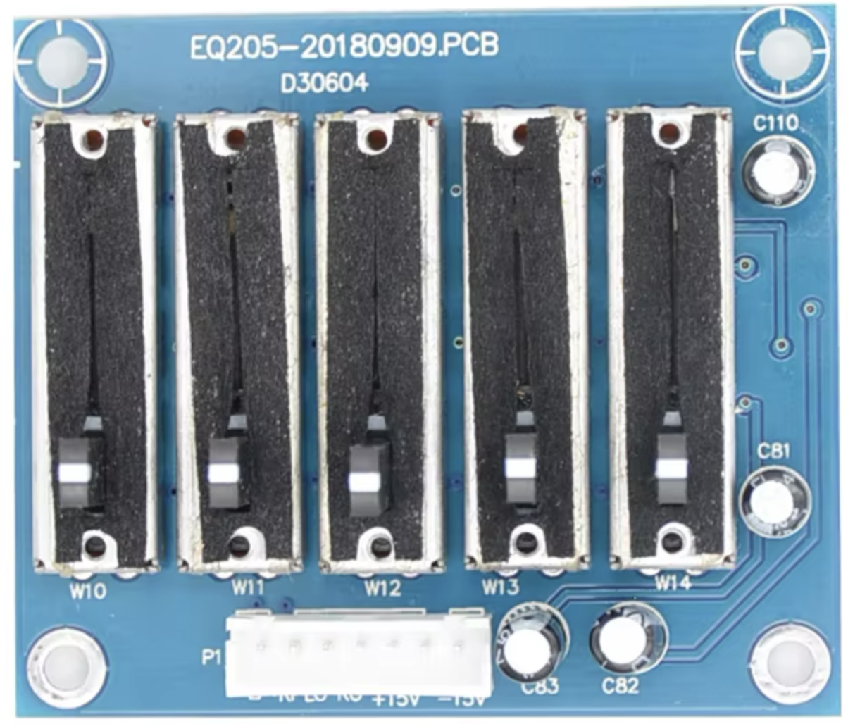
The ReYeBu 5 Band Parametric Equalizer is a versatile audio processing component designed to provide precise control over the tonal balance of audio signals. By allowing users to adjust the amplitude of audio signals across five distinct frequency bands, this equalizer is ideal for applications requiring fine-tuned sound shaping. Whether you're working on audio mixing, sound reinforcement, or custom audio projects, the ReYeBu 5 Band Parametric EQ offers a reliable and high-performance solution.
Common Applications
- Audio Mixing Consoles: Fine-tune audio signals for live performances or studio recordings.
- Home Audio Systems: Enhance the listening experience by adjusting tonal balance.
- Musical Instruments: Shape the sound of electric guitars, keyboards, or other instruments.
- DIY Audio Projects: Integrate into custom audio systems for precise sound control.
- Broadcasting: Optimize audio signals for radio or television transmission.
Technical Specifications
The ReYeBu 5 Band Parametric Equalizer is designed for ease of integration into audio systems. Below are the key technical details and pin configurations.
Key Technical Details
| Parameter | Value |
|---|---|
| Operating Voltage | 5V DC |
| Operating Current | 20mA (typical) |
| Frequency Bands | 5 (Low, Low-Mid, Mid, High-Mid, High) |
| Frequency Range | 20 Hz to 20 kHz |
| Gain Adjustment Range | ±12 dB per band |
| Input Impedance | 10 kΩ |
| Output Impedance | 1 kΩ |
| Signal-to-Noise Ratio | >90 dB |
| Total Harmonic Distortion | <0.01% |
| PCB Dimensions | 50mm x 30mm x 10mm |
Pin Configuration
The ReYeBu 5 Band Parametric Equalizer has a simple pinout for easy integration. Below is the pin configuration:
| Pin | Name | Description |
|---|---|---|
| 1 | VCC | Power supply input (5V DC). |
| 2 | GND | Ground connection. |
| 3 | AUDIO_IN | Audio signal input. |
| 4 | AUDIO_OUT | Equalized audio signal output. |
| 5 | BAND1_CTRL | Control pin for the first frequency band (Low frequencies). |
| 6 | BAND2_CTRL | Control pin for the second frequency band (Low-Mid frequencies). |
| 7 | BAND3_CTRL | Control pin for the third frequency band (Mid frequencies). |
| 8 | BAND4_CTRL | Control pin for the fourth frequency band (High-Mid frequencies). |
| 9 | BAND5_CTRL | Control pin for the fifth frequency band (High frequencies). |
Usage Instructions
How to Use the ReYeBu 5 Band Parametric Equalizer
- Power the Equalizer: Connect the
VCCpin to a 5V DC power source and theGNDpin to ground. - Input Audio Signal: Feed the audio signal into the
AUDIO_INpin. Ensure the input signal is within the acceptable voltage range. - Adjust Frequency Bands:
- Use the
BANDx_CTRLpins (wherexis 1 to 5) to adjust the gain for each frequency band. - These control pins can be connected to potentiometers, microcontrollers, or other control interfaces.
- Use the
- Output Equalized Signal: The processed audio signal will be available at the
AUDIO_OUTpin. - Integration with Microcontrollers: The control pins can be interfaced with microcontrollers like Arduino for dynamic adjustments.
Important Considerations
- Power Supply: Ensure a stable 5V DC power source to avoid noise or distortion.
- Signal Levels: Avoid overdriving the input signal to prevent clipping or distortion.
- Grounding: Proper grounding is essential to minimize noise and interference.
- Control Interface: Use high-quality potentiometers or digital controllers for precise adjustments.
Example: Using the Equalizer with Arduino UNO
The ReYeBu 5 Band Parametric Equalizer can be controlled using an Arduino UNO. Below is an example of how to adjust the gain of each frequency band using PWM signals.
Circuit Diagram
- Connect the
VCCandGNDpins of the equalizer to the Arduino's5VandGNDpins, respectively. - Connect the
BANDx_CTRLpins to the Arduino's PWM-capable pins (e.g., D3, D5, D6, D9, D10).
Arduino Code Example
// ReYeBu 5 Band Parametric Equalizer Control with Arduino UNO
// This code adjusts the gain of each frequency band using PWM signals.

#define BAND1_CTRL 3  // Pin for Low frequencies
#define BAND2_CTRL 5  // Pin for Low-Mid frequencies
#define BAND3_CTRL 6  // Pin for Mid frequencies
#define BAND4_CTRL 9  // Pin for High-Mid frequencies
#define BAND5_CTRL 10 // Pin for High frequencies

void setup() {
  // Set control pins as output
  pinMode(BAND1_CTRL, OUTPUT);
  pinMode(BAND2_CTRL, OUTPUT);
  pinMode(BAND3_CTRL, OUTPUT);
  pinMode(BAND4_CTRL, OUTPUT);
  pinMode(BAND5_CTRL, OUTPUT);
}

void loop() {
  // Example: Sweep gain for each band from 0% to 100%
  for (int dutyCycle = 0; dutyCycle <= 255; dutyCycle++) {
    analogWrite(BAND1_CTRL, dutyCycle); // Adjust Low frequencies
    analogWrite(BAND2_CTRL, dutyCycle); // Adjust Low-Mid frequencies
    analogWrite(BAND3_CTRL, dutyCycle); // Adjust Mid frequencies
    analogWrite(BAND4_CTRL, dutyCycle); // Adjust High-Mid frequencies
    analogWrite(BAND5_CTRL, dutyCycle); // Adjust High frequencies
    delay(10); // Small delay for smooth transition
  }
}
Troubleshooting and FAQs
Common Issues and Solutions
| Issue | Possible Cause | Solution |
|---|---|---|
| No audio output | Incorrect wiring or no power supply | Verify all connections and ensure a stable 5V DC power supply. |
| Distorted audio | Input signal too high or power instability | Reduce input signal amplitude and check the power source. |
| Noise or interference | Poor grounding or noisy environment | Ensure proper grounding and use shielded cables for audio connections. |
| Uneven frequency response | Incorrect control pin adjustments | Verify the control signals and adjust the gain for each band appropriately. |
FAQs
Can I use a 3.3V power supply?
- No, the equalizer requires a 5V DC power supply for proper operation.
What type of potentiometers should I use for manual control?
- Use 10kΩ linear potentiometers for smooth and precise adjustments.
Can I use this equalizer with a Raspberry Pi?
- Yes, the control pins can be interfaced with the Raspberry Pi's GPIO pins using PWM.
What is the maximum input signal level?
- The maximum input signal level is 1V RMS. Exceeding this may cause distortion.
Conclusion
The ReYeBu 5 Band Parametric Equalizer is a powerful and flexible tool for audio signal processing. Its ability to adjust five distinct frequency bands makes it suitable for a wide range of applications, from professional audio mixing to DIY projects. By following the guidelines in this documentation, users can easily integrate and optimize the equalizer for their specific needs. For further assistance, refer to the troubleshooting section or contact ReYeBu support.
Explore Projects Built with 5 Band Parametric EQ

Explore Projects Built with 5 Band Parametric EQ