How to Use ESP8266 ESP-201 WiFi Module: Examples, Pinouts, and Specs
Introduction
The ESP8266 ESP-201 WiFi Module is a self-contained wireless network controller that can add networking capabilities to existing devices or be used in the creation of Internet of Things (IoT) projects. With its powerful ESP8266 chipset, it offers WiFi connectivity, enabling devices to connect to the internet or communicate with each other within a local network. This module is particularly popular among hobbyists and professionals for its ease of use, affordability, and flexibility in various applications such as home automation, sensor networks, and industrial control systems.
Explore Projects Built with ESP8266 ESP-201 WiFi Module


Explore Projects Built with ESP8266 ESP-201 WiFi Module
Technical Specifications
Key Technical Details
- Operating Voltage: 3.3V
- Digital I/O Pins: 11
- Analog Input Pins: 1 (Input voltage range: 0 to 1V)
- WiFi Protocols: 802.11 b/g/n
- Frequency Range: 2.4 GHz - 2.5 GHz
- Flash Memory: 1MB (default)
- Operating Current: Average: 80 mA
- Integrated TCP/IP protocol stack
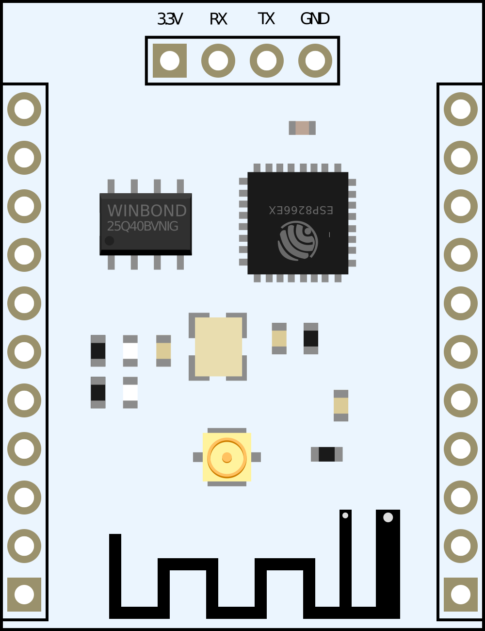
Pin Configuration and Descriptions
| Pin Number | Name | Description |
|---|---|---|
| 1 | GND | Ground |
| 2 | GPIO2 | General Purpose Input/Output 2 |
| 3 | GPIO0 | General Purpose Input/Output 0 |
| 4 | RX | UART Receive Pin |
| 5 | TX | UART Transmit Pin |
| 6 | CH_PD | Chip Power-down Pin |
| 7 | RST | Reset Pin |
| 8 | VCC | 3.3V Power Supply |
| 9 | SDIO | SD Card Interface (optional use) |
| 10 | SCLK | SPI Clock (optional use) |
| 11 | MISO | SPI MISO (Master In Slave Out, optional use) |
| 12 | MOSI | SPI MOSI (Master Out Slave In, optional use) |
| 13 | CS | SPI Chip Select (optional use) |
Usage Instructions
Basic Setup
- Power Supply: Connect the VCC pin to a stable 3.3V power source and the GND pin to the ground.
- UART Communication: Connect the RX and TX pins to a USB-to-Serial converter for programming and debugging.
- Boot Mode Configuration: To enter the UART download mode, GPIO0 must be low during power-up or reset. For normal operation, GPIO0 must be high.
- Reset: The RST pin can be connected to a push-button to enable manual resetting of the module.
Programming
The ESP8266 ESP-201 can be programmed using the Arduino IDE or other development environments that support the ESP8266 platform. To program the module with the Arduino IDE:
- Install the ESP8266 board package in the Arduino IDE.
- Select the correct board and port in the IDE.
- Write or load your program (sketch) and upload it to the module.
Example Code
Here is a simple example of how to connect the ESP8266 ESP-201 to a Wi-Fi network and make an HTTP GET request using the Arduino IDE:
#include <ESP8266WiFi.h>

const char* ssid = "yourSSID"; // Replace with your WiFi network name
const char* password = "yourPASSWORD"; // Replace with your WiFi password

void setup() {
  Serial.begin(115200);
  WiFi.begin(ssid, password);

  while (WiFi.status() != WL_CONNECTED) {
    delay(500);
    Serial.print(".");
  }

  Serial.println("");
  Serial.println("WiFi connected");
  Serial.println("IP address: ");
  Serial.println(WiFi.localIP());

  // Make an HTTP GET request
  WiFiClient client;
  if (!client.connect("example.com", 80)) {
    Serial.println("Connection failed");
    return;
  }

  client.println("GET / HTTP/1.1");
  client.println("Host: example.com");
  client.println("Connection: close");
  client.println();
}

void loop() {
  // Nothing here for this simple example
}
Important Considerations and Best Practices
- Always ensure that the power supply is 3.3V, as higher voltages can damage the module.
- Use a logic level converter if you need to interface the ESP8266 with 5V logic devices.
- It is recommended to use an external antenna if the module is placed in an environment with poor WiFi signal.
- Avoid placing the module near materials that can interfere with the WiFi signal, such as metal objects or thick walls.
Troubleshooting and FAQs
Common Issues
- Module not responding: Ensure that the power supply is adequate and the GPIO0 pin is correctly configured for the desired mode.
- Cannot connect to WiFi: Verify that the SSID and password are correct and that the WiFi network is within range.
- Serial communication issues: Check the baud rate and the connection of the RX and TX pins.
Solutions and Tips
- If the module is not booting, check the CH_PD pin to ensure it is pulled high.
- For persistent issues with uploading sketches, try changing the Flash Size or Reset Method in the Arduino IDE settings for the ESP8266 board.
- Use external power supply if the USB-to-Serial converter cannot provide sufficient current.
FAQs
Q: Can the ESP8266 ESP-201 be used with a 5V power supply? A: No, it requires a 3.3V power supply. Using a 5V supply can permanently damage the module.
Q: How can I extend the range of the WiFi signal? A: You can attach an external antenna to the module or ensure that the module is placed in an open area without obstructions.
Q: Is it possible to use the ESP8266 ESP-201 with the Arduino UNO? A: Yes, but you will need a logic level converter to connect the ESP8266's 3.3V logic to the Arduino UNO's 5V logic levels.
Q: Can I use the ESP8266 ESP-201 as a standalone microcontroller? A: Yes, the ESP8266 is a fully-fledged microcontroller with built-in WiFi capabilities and can be used without an additional microcontroller.