
How to Use LinkIt ONE board: Examples, Pinouts, and Specs
 Design with LinkIt ONE board in Cirkit Designer
Introduction
The LinkIt ONE board, manufactured by Seeed Studio, is a versatile development platform designed for Internet of Things (IoT) applications and rapid prototyping. It integrates multiple connectivity options, including Wi-Fi, GSM, GPS, and Bluetooth, making it an all-in-one solution for developers. The board is powered by the MediaTek Aster (MT2502) chipset and is compatible with the Arduino ecosystem, allowing seamless integration with existing Arduino libraries and tools.
Explore Projects Built with LinkIt ONE board
 Open Project in Cirkit Designer
 Open Project in Cirkit Designer
 Open Project in Cirkit Designer
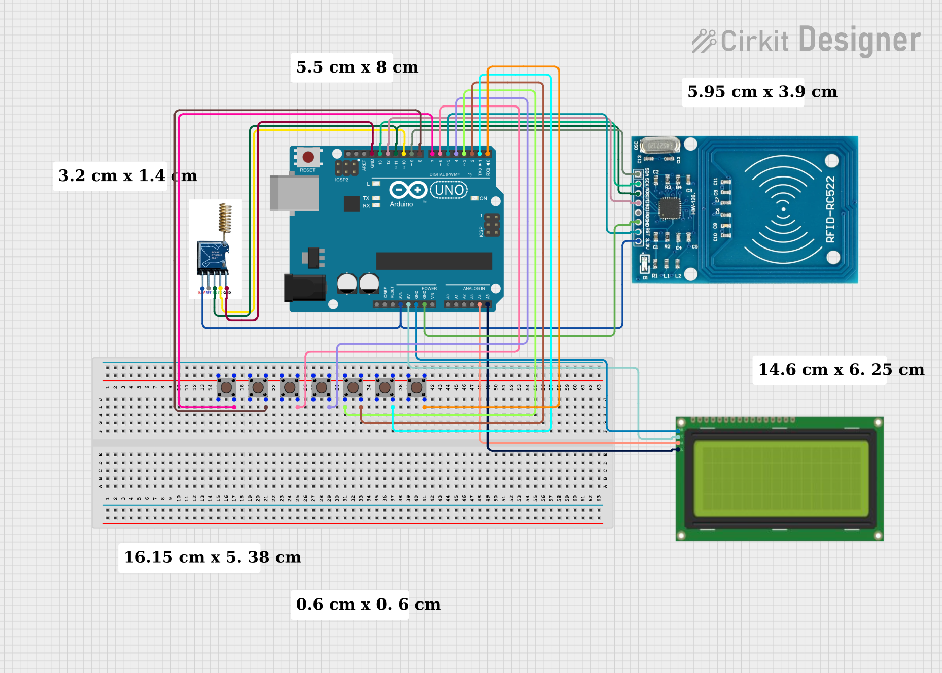 Open Project in Cirkit Designer
Explore Projects Built with LinkIt ONE board
Open Project in Cirkit DesignerOpen Project in Cirkit DesignerOpen Project in Cirkit DesignerOpen Project in Cirkit DesignerCommon Applications and Use Cases
- IoT device prototyping
- Smart home automation systems
- GPS tracking and navigation
- Wearable technology
- Remote monitoring and control systems
- Wireless data transmission and logging
Technical Specifications
Key Technical Details
| Specification | Details |
|---|---|
| Microcontroller | MediaTek Aster (MT2502) |
| Operating Voltage | 3.3V |
| Input Voltage Range | 5V (via USB) or 3.7V Li-Po battery |
| Connectivity | Wi-Fi (802.11 b/g/n), GSM/GPRS, GPS, Bluetooth 2.1 + EDR |
| Flash Memory | 16 MB |
| RAM | 4 MB |
| Digital I/O Pins | 14 (6 of which support PWM) |
| Analog Input Pins | 3 |
| Communication Interfaces | UART, I2C, SPI |
| Power Supply Options | USB or Li-Po battery |
| Dimensions | 85.6 mm x 54 mm |
| Weight | 52 g |
Pin Configuration and Descriptions
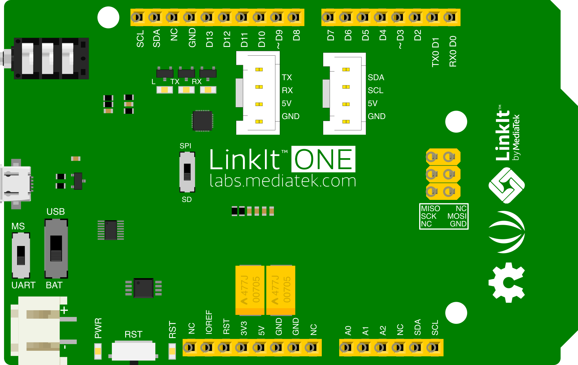
The LinkIt ONE board features a pin layout similar to Arduino boards, making it easy to use with existing shields and accessories. Below is the pin configuration:
| Pin Number | Pin Name | Description |
|---|---|---|
| 0-13 | Digital I/O | General-purpose digital input/output pins. Pins 3, 5, 6, 9, 10, and 11 support PWM. |
| A0-A2 | Analog Input | Analog input pins with a resolution of 10 bits. |
| TX/RX | UART | Serial communication pins (TX for transmit, RX for receive). |
| SDA/SCL | I2C | I2C communication pins (SDA for data, SCL for clock). |
| MOSI/MISO/SCK | SPI | SPI communication pins for high-speed data transfer. |
| VIN | Power Input | External power input (5V). |
| 3.3V/5V | Power Output | Regulated power output for external components. |
| GND | Ground | Common ground pin. |
Usage Instructions
How to Use the LinkIt ONE in a Circuit
Powering the Board:
- Connect the board to your computer via a micro-USB cable for development and power.
- Alternatively, use a 3.7V Li-Po battery for portable applications.
- Ensure the power switch is set to the correct position (USB or BAT).
Programming the Board:
- Install the LinkIt ONE SDK and drivers from the Seeed Studio website.
- Use the Arduino IDE to write and upload code to the board. Select "LinkIt ONE" as the board type in the IDE.
Connecting Peripherals:
- Use the digital and analog pins to connect sensors, actuators, and other peripherals.
- For wireless communication, configure the Wi-Fi, GSM, GPS, or Bluetooth modules as needed.
Example Circuit:
- Connect an LED to pin 13 with a 220-ohm resistor.
- Use the following code to blink the LED:
// Example: Blink an LED connected to pin 13 on the LinkIt ONE board

void setup() {
  pinMode(13, OUTPUT); // Set pin 13 as an output
}

void loop() {
  digitalWrite(13, HIGH); // Turn the LED on
  delay(1000);            // Wait for 1 second
  digitalWrite(13, LOW);  // Turn the LED off
  delay(1000);            // Wait for 1 second
}
Important Considerations and Best Practices
- Power Supply: Always ensure the board is powered correctly to avoid damage. Use a Li-Po battery with the recommended voltage and capacity.
- Antenna Connections: For GSM, GPS, and Wi-Fi functionality, connect the appropriate antennas to the board.
- Firmware Updates: Regularly check for firmware updates from Seeed Studio to ensure optimal performance and compatibility.
- Heat Management: Avoid prolonged use in high-temperature environments to prevent overheating.
Troubleshooting and FAQs
Common Issues and Solutions
| Issue | Possible Cause | Solution |
|---|---|---|
| Board not detected by the computer | Missing drivers or faulty USB cable | Install the LinkIt ONE drivers and check the USB cable/port. |
| GSM module not working | Antenna not connected or poor signal | Ensure the GSM antenna is securely connected and check signal strength. |
| GPS not providing location data | Poor satellite visibility | Use the GPS module outdoors or near a window for better reception. |
| Code upload fails | Incorrect board or port selected | Verify that "LinkIt ONE" is selected as the board in the Arduino IDE. |
| Wi-Fi connection issues | Incorrect SSID/password or interference | Double-check the Wi-Fi credentials and reduce interference sources. |
FAQs
Can I use Arduino shields with the LinkIt ONE?
Yes, the LinkIt ONE is compatible with most Arduino shields due to its similar pin layout.What is the maximum range of the Bluetooth module?
The Bluetooth module supports a range of up to 10 meters in open spaces.How do I switch between USB and battery power?
Use the power switch on the board to toggle between USB (for development) and BAT (for battery).Can I use the board without a Li-Po battery?
Yes, the board can be powered solely via USB, but certain features like GSM may require a battery.Where can I find additional resources?
Visit the Seeed Studio website for detailed documentation, SDKs, and community support.
By following this documentation, you can effectively utilize the LinkIt ONE board for your IoT and prototyping projects.