How to Use ESP32 T-Internet-Poe: Examples, Pinouts, and Specs
Introduction
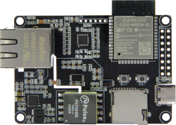
The ESP32 T-Internet-PoE by LILYGO (Part ID: T-Internet-POE) is a versatile microcontroller board designed for Internet of Things (IoT) applications. It combines the powerful ESP32 microcontroller with integrated Wi-Fi and Bluetooth capabilities, making it ideal for wireless communication. Additionally, it features Power over Ethernet (PoE) support, enabling the board to receive both power and data through a single Ethernet cable. This simplifies installation, reduces wiring complexity, and makes it suitable for remote or hard-to-reach deployments.
Explore Projects Built with ESP32 T-Internet-Poe


Explore Projects Built with ESP32 T-Internet-Poe
Common Applications and Use Cases
- Smart home automation systems
- Industrial IoT (IIoT) devices
- Remote environmental monitoring
- Networked sensors and actuators
- Smart lighting and energy management
- Security and surveillance systems
Technical Specifications
Below are the key technical details of the ESP32 T-Internet-PoE:
| Specification | Details |
|---|---|
| Microcontroller | ESP32 dual-core processor with Xtensa LX6 architecture |
| Clock Speed | Up to 240 MHz |
| Flash Memory | 4 MB (varies by model) |
| SRAM | 520 KB |
| Connectivity | Wi-Fi (802.11 b/g/n), Bluetooth 4.2 (Classic + BLE) |
| Ethernet | 10/100 Mbps Ethernet with PoE support |
| Power Input | PoE (IEEE 802.3af) or 5V via USB-C |
| GPIO Pins | 20+ GPIO pins with multiple functions (PWM, ADC, I2C, SPI, UART, etc.) |
| Operating Voltage | 3.3V (logic level) |
| Dimensions | 60mm x 25mm x 10mm |
| Operating Temperature | -40°C to 85°C |
Pin Configuration and Descriptions
The ESP32 T-Internet-PoE features a variety of pins for interfacing with peripherals. Below is the pinout description:
| Pin Name | Function | Description |
|---|---|---|
| VIN | Power Input | 5V input via USB-C or external power source. |
| GND | Ground | Common ground for the circuit. |
| GPIO0 | General Purpose I/O | Can be used for input/output, ADC, or other functions. |
| GPIO1 | General Purpose I/O | UART TX pin (default) or configurable for other functions. |
| GPIO2 | General Purpose I/O | UART RX pin (default) or configurable for other functions. |
| GPIO12-19 | General Purpose I/O | Multi-purpose pins for PWM, I2C, SPI, ADC, etc. |
| TX/RX | UART Communication | Dedicated UART pins for serial communication. |
| EN | Enable | Used to enable or reset the ESP32 module. |
| Ethernet TX+ | Ethernet Transmit Positive | Ethernet data transmission (PoE). |
| Ethernet TX- | Ethernet Transmit Negative | Ethernet data transmission (PoE). |
| Ethernet RX+ | Ethernet Receive Positive | Ethernet data reception (PoE). |
| Ethernet RX- | Ethernet Receive Negative | Ethernet data reception (PoE). |
Usage Instructions
How to Use the ESP32 T-Internet-PoE in a Circuit
Powering the Board:
- Connect the board to a PoE-enabled Ethernet switch or injector to provide both power and data.
- Alternatively, power the board via the USB-C port using a 5V power source.
Connecting Peripherals:
- Use the GPIO pins to connect sensors, actuators, or other peripherals.
- Ensure that the logic level of connected devices is 3.3V to avoid damaging the board.
Programming the Board:
- The ESP32 T-Internet-PoE can be programmed using the Arduino IDE, PlatformIO, or the ESP-IDF framework.
- Connect the board to your computer via USB-C and select the appropriate COM port in your development environment.
Ethernet Configuration:
- To use the Ethernet functionality, connect the board to a network using an Ethernet cable.
- Configure the Ethernet settings in your code (e.g., static IP or DHCP).
Important Considerations and Best Practices
- PoE Compatibility: Ensure that your Ethernet switch or injector supports IEEE 802.3af PoE standard.
- Voltage Levels: Avoid applying voltages higher than 3.3V to the GPIO pins.
- Heat Management: If the board operates in high-temperature environments, consider adding a heatsink for better thermal performance.
- Firmware Updates: Regularly update the firmware to ensure compatibility with the latest features and security patches.
Example Code for Arduino IDE
Below is an example of how to configure the ESP32 T-Internet-PoE for basic Ethernet communication:
#include <ETH.h> // Include the Ethernet library for ESP32

// Define Ethernet configuration
#define ETH_CLK_MODE ETH_CLOCK_GPIO17_OUT // Set clock mode
#define ETH_PHY_POWER 12                  // GPIO pin for PHY power

// Callback function for Ethernet events
void WiFiEvent(WiFiEvent_t event) {
  switch (event) {
    case SYSTEM_EVENT_ETH_CONNECTED:
      Serial.println("Ethernet connected");
      break;
    case SYSTEM_EVENT_ETH_DISCONNECTED:
      Serial.println("Ethernet disconnected");
      break;
    case SYSTEM_EVENT_ETH_GOT_IP:
      Serial.print("IP Address: ");
      Serial.println(ETH.localIP());
      break;
    default:
      break;
  }
}

void setup() {
  Serial.begin(115200); // Initialize serial communication
  WiFi.onEvent(WiFiEvent); // Register Ethernet event callback

  // Start Ethernet
  ETH.begin(ETH_PHY_ADDR, ETH_PHY_POWER, ETH_CLK_MODE, ETH_PHY_TYPE);
  Serial.println("Ethernet initialized");
}

void loop() {
  // Main loop does nothing; Ethernet events are handled in the callback
}
Troubleshooting and FAQs
Common Issues and Solutions
Board Not Powering On:
- Ensure that the PoE switch or injector is IEEE 802.3af compliant.
- If using USB-C, verify that the power source provides at least 5V/1A.
Ethernet Not Working:
- Check the Ethernet cable for damage or improper connection.
- Verify that the network settings (e.g., IP address, subnet mask) are correctly configured in your code.
Wi-Fi or Bluetooth Not Connecting:
- Ensure that the correct SSID and password are used for Wi-Fi.
- Check for interference or weak signal strength in the deployment area.
GPIO Pins Not Responding:
- Confirm that the pins are correctly configured in your code.
- Avoid exceeding the 3.3V logic level on GPIO pins.
FAQs
Q: Can I use the ESP32 T-Internet-PoE without PoE?
A: Yes, the board can be powered via the USB-C port using a 5V power source.
Q: Does the board support over-the-air (OTA) updates?
A: Yes, the ESP32 supports OTA updates, which can be implemented using the Arduino IDE or ESP-IDF.
Q: What is the maximum current output of the GPIO pins?
A: Each GPIO pin can source or sink up to 12mA. For higher currents, use external drivers or transistors.
Q: Can I use the board in outdoor environments?
A: The board is not weatherproof. For outdoor use, enclose it in a weather-resistant case.