
How to Use DSP33CK64CM105: Examples, Pinouts, and Specs
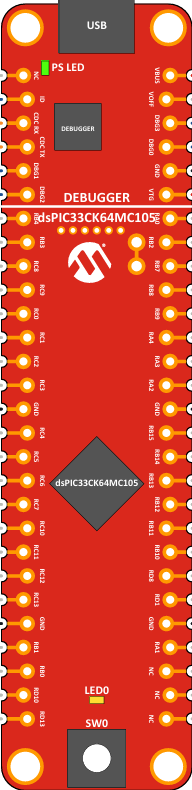
 Design with DSP33CK64CM105 in Cirkit Designer
Introduction
The DSP33CK64CM105 is a high-performance digital signal processor (DSP) designed for advanced signal processing applications. Featuring a 64-bit architecture, this component is optimized for low power consumption, making it ideal for applications requiring efficient and reliable signal processing. Its robust design and versatile features make it suitable for a wide range of industries, including telecommunications, audio processing, industrial automation, and embedded systems.
Explore Projects Built with DSP33CK64CM105
 Open Project in Cirkit Designer
 Open Project in Cirkit Designer
 Open Project in Cirkit Designer
 Open Project in Cirkit Designer
Explore Projects Built with DSP33CK64CM105
Open Project in Cirkit DesignerOpen Project in Cirkit DesignerOpen Project in Cirkit DesignerOpen Project in Cirkit DesignerCommon Applications
- Audio signal processing (e.g., equalizers, noise reduction, and audio effects)
- Telecommunications (e.g., modulation, demodulation, and encoding)
- Motor control and industrial automation
- Image and video processing
- Embedded systems requiring real-time data analysis
Technical Specifications
Key Technical Details
| Parameter | Value |
|---|---|
| Architecture | 64-bit |
| Clock Speed | Up to 200 MHz |
| Operating Voltage | 1.8V (core), 3.3V (I/O) |
| Power Consumption | Low power, optimized for energy efficiency |
| Memory | 64 KB RAM, 256 KB Flash |
| Communication Interfaces | UART, SPI, I2C, CAN |
| GPIO Pins | 16 configurable pins |
| Package Type | 64-pin TQFP |
| Operating Temperature | -40°C to +85°C |
Pin Configuration and Descriptions
The DSP33CK64CM105 comes in a 64-pin TQFP package. Below is a summary of the pin configuration:
| Pin Number | Pin Name | Description |
|---|---|---|
| 1 | VDD | Core power supply (1.8V) |
| 2 | VSS | Ground |
| 3 | GPIO1 | General-purpose I/O pin |
| 4 | GPIO2 | General-purpose I/O pin |
| 5 | UART_TX | UART transmit pin |
| 6 | UART_RX | UART receive pin |
| 7 | SPI_MOSI | SPI Master Out Slave In |
| 8 | SPI_MISO | SPI Master In Slave Out |
| 9 | SPI_CLK | SPI clock |
| 10 | I2C_SCL | I2C clock |
| 11 | I2C_SDA | I2C data |
| 12 | CAN_TX | CAN transmit pin |
| 13 | CAN_RX | CAN receive pin |
| 14 | RESET | Reset input |
| 15 | XTAL_IN | Crystal oscillator input |
| 16 | XTAL_OUT | Crystal oscillator output |
| ... | ... | ... (remaining pins follow similar format) |
Refer to the manufacturer's datasheet for a complete pinout and detailed descriptions.
Usage Instructions
How to Use the DSP33CK64CM105 in a Circuit
- Power Supply: Connect the core power supply (VDD) to 1.8V and the I/O power supply to 3.3V. Ensure proper decoupling capacitors are placed near the power pins to reduce noise.
- Clock Source: Use an external crystal oscillator or clock source connected to the XTAL_IN and XTAL_OUT pins. A typical crystal frequency is 16 MHz.
- Communication Interfaces: Configure the desired communication protocol (UART, SPI, I2C, or CAN) by connecting the appropriate pins to external devices.
- GPIO Configuration: Set up the GPIO pins as input or output based on your application requirements. Use pull-up or pull-down resistors if necessary.
- Programming: Load your program into the DSP using the UART or SPI interface. Ensure the firmware is optimized for the 64-bit architecture.
Important Considerations and Best Practices
- Heat Management: Although the DSP33CK64CM105 is optimized for low power consumption, ensure proper heat dissipation in high-performance applications.
- Signal Integrity: Use short and properly routed traces for high-speed signals like SPI and UART to minimize noise and signal degradation.
- Debugging: Utilize the debugging interface provided by the manufacturer for real-time debugging and performance analysis.
- Power Sequencing: Apply the core voltage (1.8V) before the I/O voltage (3.3V) to avoid damage to the device.
Example: Interfacing with Arduino UNO
The DSP33CK64CM105 can be connected to an Arduino UNO for basic communication via UART. Below is an example Arduino sketch to send data to the DSP:
// Example: Sending data to DSP33CK64CM105 via UART
// Ensure the DSP's UART_RX pin is connected to Arduino's TX pin (D1)
// and the DSP's UART_TX pin is connected to Arduino's RX pin (D0).

void setup() {
  Serial.begin(9600); // Initialize UART communication at 9600 baud rate
  delay(1000);        // Wait for DSP to initialize
  Serial.println("Hello, DSP33CK64CM105!"); // Send a test message
}

void loop() {
  // Continuously send data to the DSP
  Serial.println("Sending data to DSP...");
  delay(1000); // Wait 1 second before sending the next message
}
Note: Ensure the voltage levels between the Arduino (5V) and DSP (3.3V) are compatible. Use a level shifter if necessary.
Troubleshooting and FAQs
Common Issues and Solutions
The DSP does not power on:
- Verify that the core (1.8V) and I/O (3.3V) power supplies are correctly connected.
- Check for proper decoupling capacitors near the power pins.
Communication interfaces are not working:
- Ensure the correct pins are connected and configured for the desired protocol.
- Double-check the baud rate and other communication settings.
The DSP is overheating:
- Verify that the power supply voltage is within the specified range.
- Add a heatsink or improve ventilation if necessary.
Program upload fails:
- Confirm that the programming interface (e.g., UART or SPI) is correctly connected.
- Check for errors in the firmware or programming tool.
FAQs
Q: Can the DSP33CK64CM105 operate at higher clock speeds?
A: The maximum clock speed is 200 MHz. Exceeding this limit may cause instability or damage.
Q: Is the DSP compatible with 5V logic levels?
A: No, the DSP operates at 3.3V for I/O. Use a level shifter to interface with 5V devices.
Q: Can I use the DSP for real-time audio processing?
A: Yes, the DSP33CK64CM105 is well-suited for real-time audio processing applications due to its high-performance 64-bit architecture.
Q: Does the DSP support external memory?
A: The DSP has built-in 64 KB RAM and 256 KB Flash. For additional memory, external interfaces like SPI can be used to connect external memory modules.
For further assistance, refer to the manufacturer's datasheet or contact technical support.