Cirkit Designer Logo
Cirkit Designer
Your all-in-one circuit design IDE
Home / 
Component Documentation

How to Use My component: Examples, Pinouts, and Specs
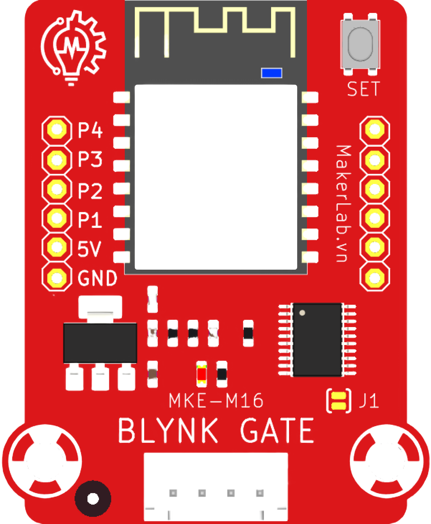
Image of My component
Cirkit Designer LogoDesign with My component in Cirkit Designer

Introduction

My Component is a versatile and generic electronic component designed to serve a specific function within a variety of electronic circuit designs. It is commonly used in both hobbyist projects and professional applications due to its reliability and ease of use. Typical applications for My Component include signal processing, power regulation, and interfacing with other electronic devices.

Explore Projects Built with My component
Use Cirkit Designer to design, explore, and prototype these projects online. Some projects support real-time simulation. Click "Open Project" to start designing instantly!
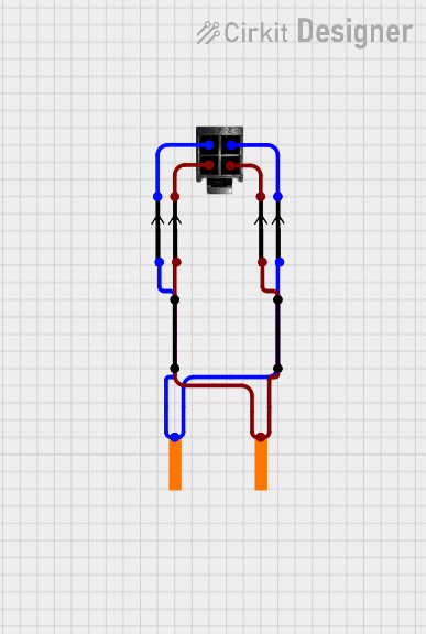
4-Pin Connector Circuit for Edge Detection
Image of 4pin: A project utilizing My component in a practical application
This circuit appears to be a simple interconnection of pins and points, with a 4-pin component serving as a central hub. The red and black pins of the 4-pin component are connected to various other pins and edge components, forming a basic network of connections without any active components or microcontroller logic.
Cirkit Designer LogoOpen Project in Cirkit Designer
I2C-Controlled OLED Display with External EEPROM and Interactive Pushbuttons
Image of godmode: A project utilizing My component in a practical application
This is a microcontroller-based interactive device featuring a Wemos D1 Mini, an OLED display, external EEPROM, and an I/O expander. It includes user input buttons and status LEDs, with potential MIDI interface capabilities.
Cirkit Designer LogoOpen Project in Cirkit Designer
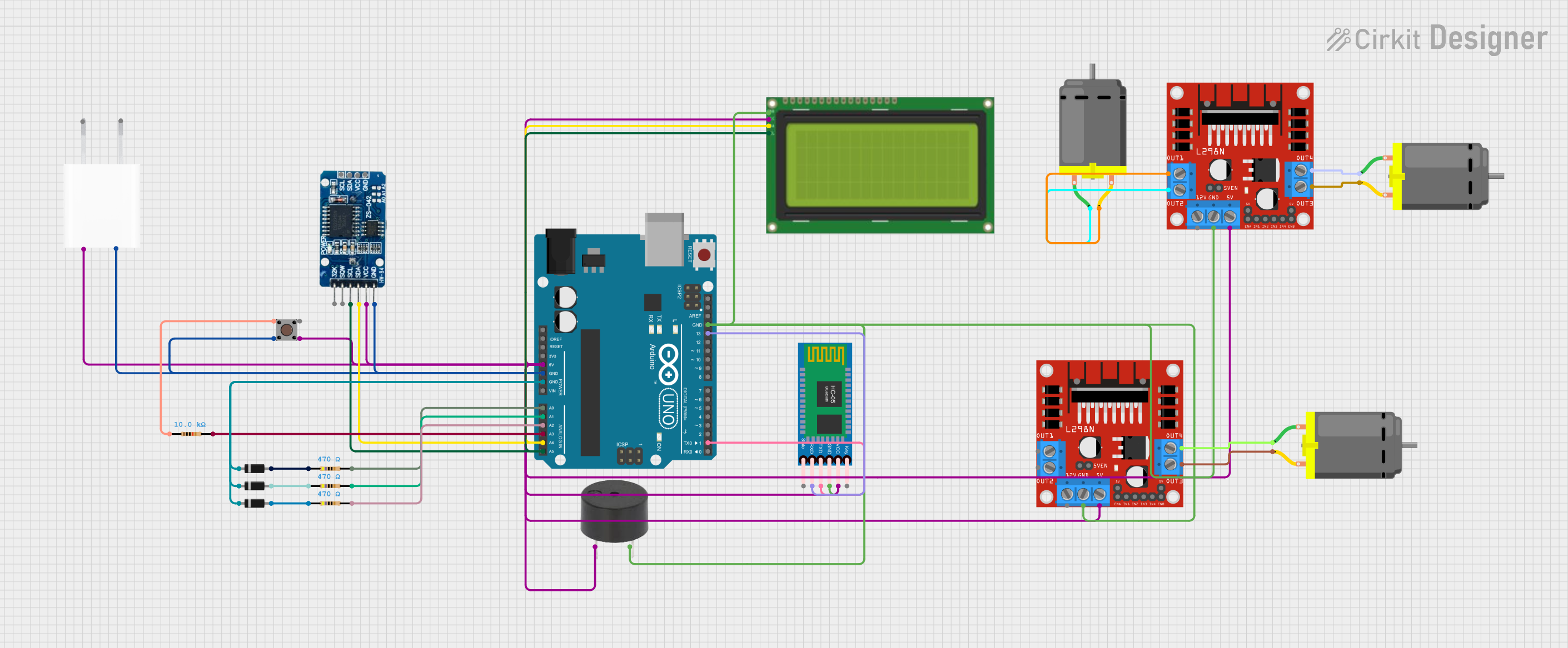
Arduino UNO-Based Smart Home Automation System with Bluetooth and RTC
Image of Pill Dispenser: A project utilizing My component in a practical application
This circuit is a microcontroller-based system using an Arduino UNO to control various components including an RTC module, Bluetooth module, LCD display, pushbutton, buzzer, and multiple DC motors via motor drivers. The system is powered by a 5V adapter and is designed for real-time monitoring and control, with communication capabilities through Bluetooth and visual feedback via the LCD.
Cirkit Designer LogoOpen Project in Cirkit Designer
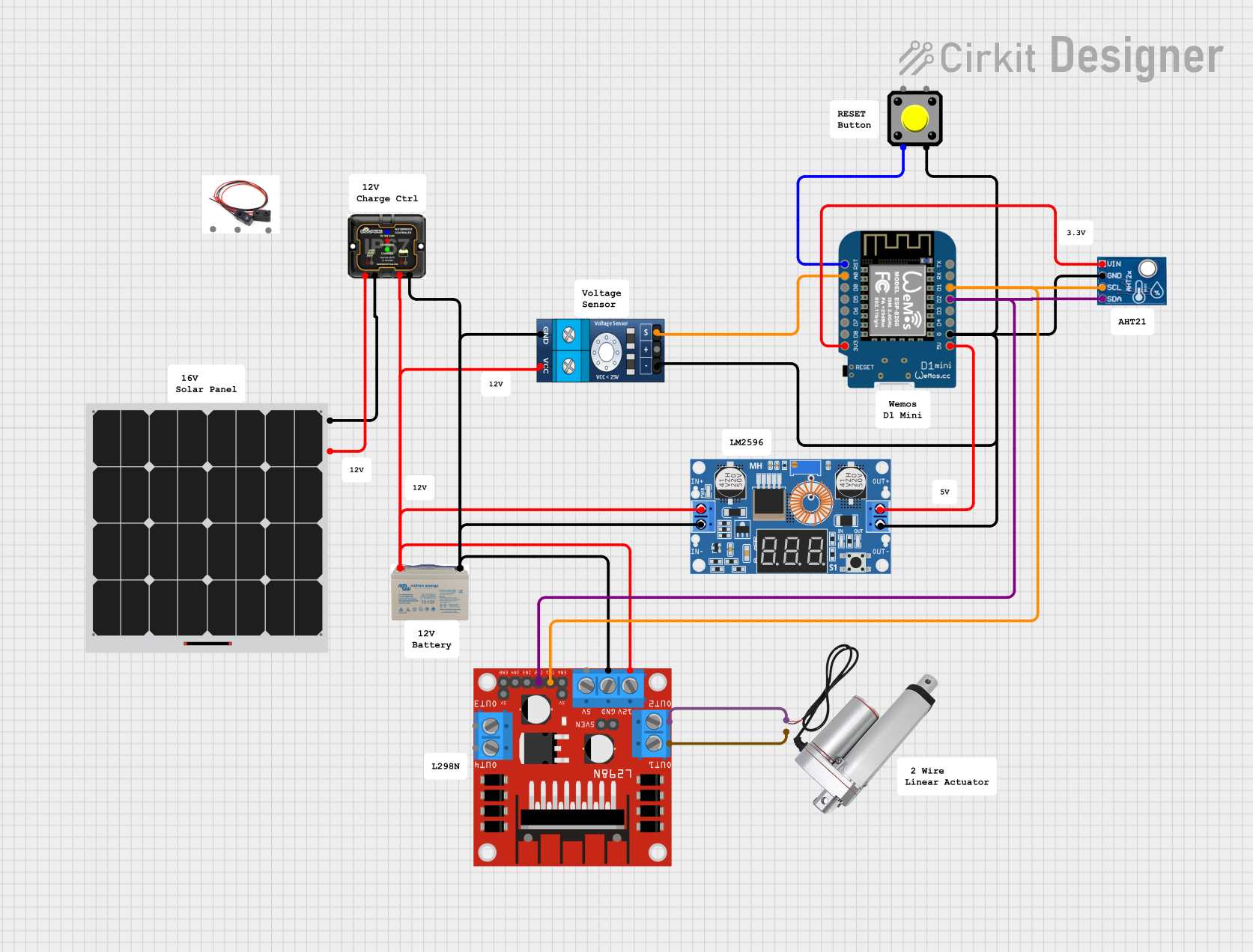
Wemos D1 Mini Based Environmental Monitoring System with Solar Charging
Image of Generator Shed Voltage & Temperature Monitor: A project utilizing My component in a practical application
This circuit features a Wemos D1 Mini microcontroller interfaced with a pushbutton, a voltage sensor, an AHT21 temperature and humidity sensor, and an L298N motor driver controlling a linear actuator. The Wemos D1 Mini is powered by a 5V supply from an XL4015 DC-DC buck converter, which steps down the voltage from a 12V AGM battery charged by a solar panel through an MPPT charge controller. The microcontroller reads the voltage sensor data and controls the actuator based on programmed logic, while the pushbutton provides user input and the AHT21 sensor monitors environmental conditions.
Cirkit Designer LogoOpen Project in Cirkit Designer

Explore Projects Built with My component

Use Cirkit Designer to design, explore, and prototype these projects online. Some projects support real-time simulation. Click "Open Project" to start designing instantly!
Image of 4pin: A project utilizing My component in a practical application
4-Pin Connector Circuit for Edge Detection
This circuit appears to be a simple interconnection of pins and points, with a 4-pin component serving as a central hub. The red and black pins of the 4-pin component are connected to various other pins and edge components, forming a basic network of connections without any active components or microcontroller logic.
Cirkit Designer LogoOpen Project in Cirkit Designer
Image of godmode: A project utilizing My component in a practical application
I2C-Controlled OLED Display with External EEPROM and Interactive Pushbuttons
This is a microcontroller-based interactive device featuring a Wemos D1 Mini, an OLED display, external EEPROM, and an I/O expander. It includes user input buttons and status LEDs, with potential MIDI interface capabilities.
Cirkit Designer LogoOpen Project in Cirkit Designer
Image of Pill Dispenser: A project utilizing My component in a practical application
Arduino UNO-Based Smart Home Automation System with Bluetooth and RTC
This circuit is a microcontroller-based system using an Arduino UNO to control various components including an RTC module, Bluetooth module, LCD display, pushbutton, buzzer, and multiple DC motors via motor drivers. The system is powered by a 5V adapter and is designed for real-time monitoring and control, with communication capabilities through Bluetooth and visual feedback via the LCD.
Cirkit Designer LogoOpen Project in Cirkit Designer
Image of Generator Shed Voltage & Temperature Monitor: A project utilizing My component in a practical application
Wemos D1 Mini Based Environmental Monitoring System with Solar Charging
This circuit features a Wemos D1 Mini microcontroller interfaced with a pushbutton, a voltage sensor, an AHT21 temperature and humidity sensor, and an L298N motor driver controlling a linear actuator. The Wemos D1 Mini is powered by a 5V supply from an XL4015 DC-DC buck converter, which steps down the voltage from a 12V AGM battery charged by a solar panel through an MPPT charge controller. The microcontroller reads the voltage sensor data and controls the actuator based on programmed logic, while the pushbutton provides user input and the AHT21 sensor monitors environmental conditions.
Cirkit Designer LogoOpen Project in Cirkit Designer

Technical Specifications

Key Technical Details

Specification Value Description
Operating Voltage 3.3V - 5V The voltage range within which the component operates safely.
Maximum Current 20mA The maximum current the component can handle without damage.
Power Rating 100mW The maximum power dissipation of the component.
Operating Temperature -40°C to 85°C The range of ambient temperatures over which the component can operate.

Pin Configuration and Descriptions

Pin Number Name Description
1 VCC Power supply input; connect to 3.3V or 5V.
2 GND Ground connection.
3 IN Input signal; accepts analog or digital signals.
4 OUT Output signal; outputs processed signal based on input.

Usage Instructions

Incorporating My Component into a Circuit

  1. Power Connections: Connect the VCC pin to a 3.3V or 5V power supply and the GND pin to the common ground in your circuit.
  2. Signal Connections: Connect the IN pin to the signal you wish to process. The OUT pin should be connected to the next stage in your circuit, such as an amplifier or microcontroller input.
  3. Mounting: Ensure that My Component is securely mounted on a printed circuit board (PCB) or breadboard to prevent movement that could lead to intermittent connections.

Best Practices

  • Use a decoupling capacitor close to the VCC pin to filter out noise from the power supply.
  • Avoid running high-current wires near the signal paths to prevent interference.
  • If the component is being used in a noisy environment, consider using shielded cables for the input and output signals.

Example Connection with Arduino UNO

// Example code for interfacing My Component with an Arduino UNO

const int inputPin = A0; // Connect My Component OUT pin to Arduino pin A0
const int outputPin = 9; // Connect Arduino pin 9 to the next stage in the circuit

void setup() {
  pinMode(inputPin, INPUT);
  pinMode(outputPin, OUTPUT);
  Serial.begin(9600);
}

void loop() {
  int sensorValue = analogRead(inputPin); // Read the processed signal from My Component
  Serial.println(sensorValue); // Print the value to the Serial Monitor
  // Implement additional processing if required
  delay(100); // Delay for stability
}

Troubleshooting and FAQs

Common Issues

  • No Output Signal: Ensure that the power supply is connected correctly and that the input signal is within the specified range.
  • Signal Distortion: Check for any potential sources of interference and ensure that the connections are secure.
  • Component Overheating: Verify that the current and power ratings are not being exceeded.

FAQs

Q: Can My Component be used with both analog and digital signals? A: Yes, My Component is designed to handle both analog and digital input signals.

Q: What should I do if My Component is not functioning as expected? A: Double-check all connections, ensure power supply is within the specified range, and consult the troubleshooting section for common issues.

Q: Is My Component compatible with breadboard prototyping? A: Yes, My Component can be used on a breadboard for prototyping purposes.

For further assistance, please contact the manufacturer's support team or refer to the detailed datasheet for My Component.