How to Use keysight MSO2014A: Examples, Pinouts, and Specs
Introduction
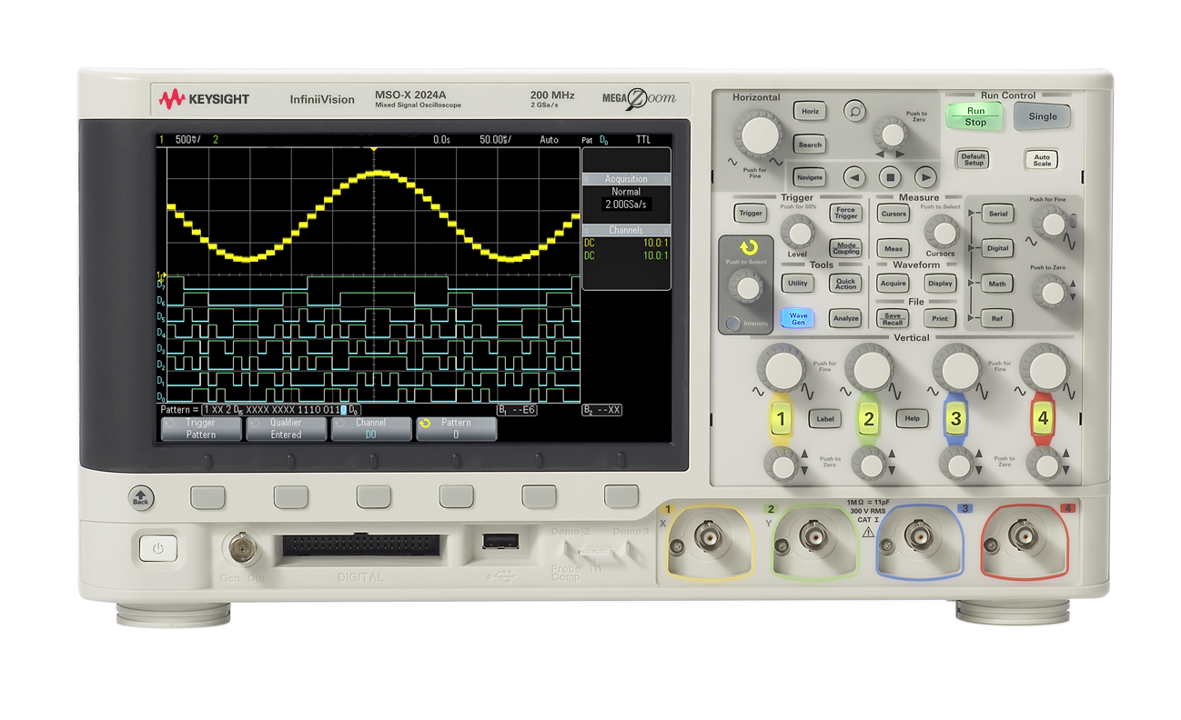
The Keysight MSO2014A is a mixed signal oscilloscope designed to provide both analog and digital signal analysis capabilities. With a 100 MHz bandwidth, 4 analog channels, and 16 digital channels, it is an ideal tool for debugging and analyzing complex electronic designs. This oscilloscope is equipped with a user-friendly interface, advanced triggering options, and a comprehensive set of measurement tools, making it suitable for engineers, technicians, and hobbyists working on a wide range of applications.
Explore Projects Built with keysight MSO2014A
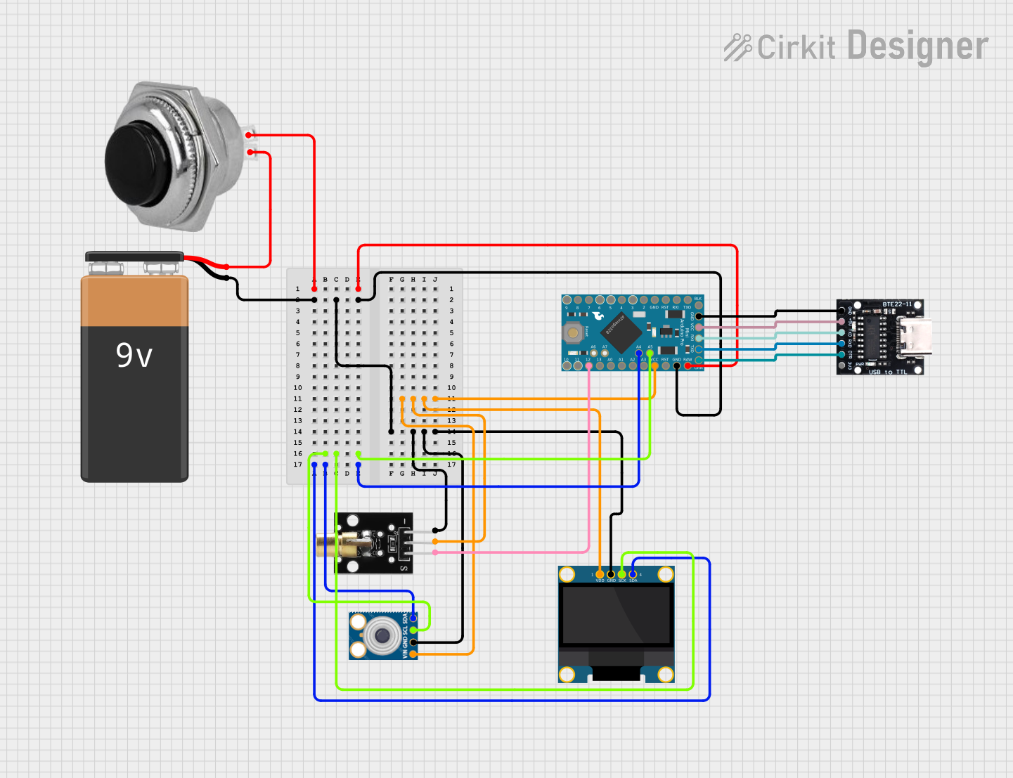
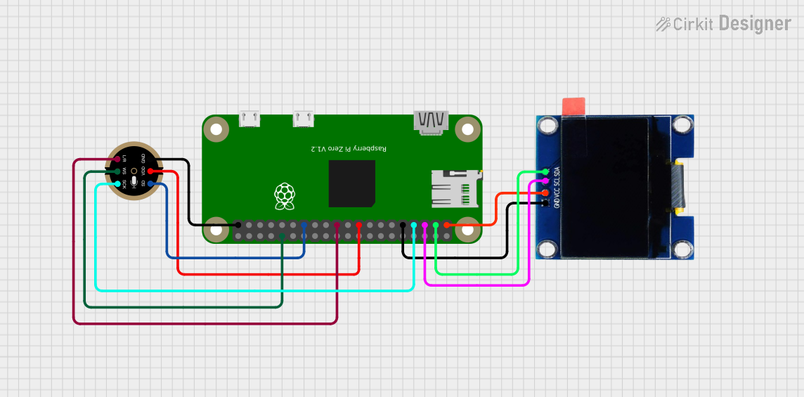


Explore Projects Built with keysight MSO2014A
Common Applications and Use Cases
- Debugging embedded systems with both analog and digital signals
- Analyzing communication protocols such as I²C, SPI, and UART
- Power electronics testing and analysis
- Signal integrity testing in high-speed designs
- Educational purposes in electronics and signal processing labs
Technical Specifications
Key Technical Details
| Specification | Value |
|---|---|
| Bandwidth | 100 MHz |
| Analog Channels | 4 |
| Digital Channels | 16 |
| Maximum Sample Rate | 2 GSa/s (giga-samples per second) |
| Memory Depth | 1 Mpts (mega-points) |
| Display | 8.5-inch WVGA (800x480) color LCD |
| Input Impedance | 1 MΩ ± 1% |
| Vertical Sensitivity | 1 mV/div to 5 V/div |
| Time Base Range | 5 ns/div to 50 s/div |
| Trigger Types | Edge, Pulse Width, Pattern, etc. |
| Connectivity | USB, LAN (optional), GPIB (optional) |
| Power Supply | 100-240 VAC, 50/60 Hz |
| Dimensions | 15.2 cm x 38.1 cm x 15.9 cm |
| Weight | 4.4 kg |
Pin Configuration and Descriptions
The Keysight MSO2014A does not have traditional "pins" like an IC but features several input/output ports and connectors. Below is a table describing the key ports:
| Port/Connector | Description |
|---|---|
| Analog Input Channels (1-4) | BNC connectors for analog signal input. Supports probes with 1 MΩ impedance. |
| Digital Input Channels (D0-D15) | 16-channel digital input via a logic probe connector. |
| USB Host Port | For connecting USB drives to save data or update firmware. |
| USB Device Port | For connecting the oscilloscope to a PC for remote control or data transfer. |
| LAN Port (optional) | Enables network connectivity for remote operation and data sharing. |
| GPIB Port (optional) | For integration into automated test systems. |
| Trigger Input/Output | External trigger input and output for synchronization with other devices. |
| Power Input | AC power input for the oscilloscope. |
Usage Instructions
How to Use the Keysight MSO2014A in a Circuit
Power On the Oscilloscope:
- Connect the power cable to the oscilloscope and plug it into an AC outlet.
- Press the power button to turn on the device.
Connect Probes:
- Attach the appropriate probes to the analog or digital input channels.
- For analog signals, use the BNC connectors (Channels 1-4).
- For digital signals, connect the logic probe to the digital input port.
Configure the Channels:
- Use the front panel controls or the touchscreen interface to enable and configure the desired channels.
- Set the vertical scale (e.g., volts/div) and horizontal time base (e.g., seconds/div) for each channel.
Set Up Triggering:
- Select a trigger source (e.g., Channel 1, external trigger).
- Choose a trigger type (e.g., edge, pulse width) and configure the trigger level.
Capture and Analyze Signals:
- Press the "Run/Stop" button to start capturing signals.
- Use the measurement tools to analyze parameters such as frequency, amplitude, and rise time.
Save or Export Data:
- Insert a USB drive into the USB host port to save screenshots or waveform data.
- Alternatively, connect the oscilloscope to a PC via USB or LAN for remote data transfer.
Important Considerations and Best Practices
- Probe Compensation: Always perform probe compensation before using the oscilloscope to ensure accurate measurements.
- Bandwidth Limiting: Use the bandwidth limit feature to reduce noise when measuring low-frequency signals.
- Grounding: Ensure proper grounding of the oscilloscope and probes to avoid measurement errors or damage.
- Firmware Updates: Regularly check for firmware updates on the Keysight website to access new features and improvements.
- Protocol Decoding: Use the built-in protocol decoding tools for analyzing communication protocols like I²C, SPI, and UART.
Example: Using the MSO2014A with an Arduino UNO
To analyze a PWM signal generated by an Arduino UNO, follow these steps:
- Connect the oscilloscope's Channel 1 probe to the Arduino's PWM output pin (e.g., Pin 9).
- Connect the probe's ground clip to the Arduino's GND pin.
- Configure the oscilloscope's Channel 1 for a vertical scale of 1 V/div and a time base of 1 ms/div.
- Set the trigger source to Channel 1 and the trigger type to "Edge" with a rising edge trigger.
Here is an example Arduino code to generate a PWM signal:
// Arduino code to generate a PWM signal on Pin 9
void setup() {
  pinMode(9, OUTPUT); // Set Pin 9 as an output
}

void loop() {
  analogWrite(9, 128); // Generate a 50% duty cycle PWM signal
  delay(1000);         // Wait for 1 second
}
Troubleshooting and FAQs
Common Issues and Solutions
| Issue | Possible Cause | Solution |
|---|---|---|
| No signal displayed on screen | Incorrect probe connection or settings | Verify probe connections and ensure the correct channel is enabled. |
| Signal appears noisy | High-frequency noise or improper grounding | Enable bandwidth limiting or check the probe's ground connection. |
| Trigger not working | Incorrect trigger source or level | Verify the trigger source and adjust the trigger level appropriately. |
| USB drive not recognized | Incompatible file system | Format the USB drive to FAT32 before use. |
| Oscilloscope freezes or crashes | Firmware issue | Restart the device and check for firmware updates on the Keysight website. |
FAQs
Can I use the MSO2014A to decode serial protocols?
- Yes, the oscilloscope supports protocol decoding for I²C, SPI, UART, and other common protocols.
What is the maximum voltage the oscilloscope can measure?
- The maximum input voltage is 300 V (DC + peak AC) with a 10:1 probe.
Can I control the oscilloscope remotely?
- Yes, the MSO2014A supports remote control via USB, LAN (optional), or GPIB (optional).
How do I update the firmware?
- Download the latest firmware from the Keysight website, copy it to a USB drive, and follow the on-screen instructions after inserting the drive into the oscilloscope.
Is the MSO2014A suitable for educational purposes?
- Absolutely! Its user-friendly interface and versatile features make it an excellent tool for teaching and learning electronics.