Cirkit Designer Logo
Cirkit Designer
Your all-in-one circuit design IDE
Home / 
Component Documentation

How to Use Relay: Examples, Pinouts, and Specs

Image of Relay
Cirkit Designer LogoDesign with Relay in Cirkit Designer

Introduction

A relay is an electromechanical switch that allows you to control a high-power or high-voltage circuit using a low-power signal. It is commonly used in applications where it is necessary to control a large power load with a smaller control signal, such as home automation systems, automotive electronics, and industrial machinery.

Explore Projects Built with Relay

Use Cirkit Designer to design, explore, and prototype these projects online. Some projects support real-time simulation. Click "Open Project" to start designing instantly!
WeMos D1 R2 Controlled Relay Switching Circuit for AC Bulb and USB Charger
Image of Hand Gesture Light: A project utilizing Relay in a practical application
This circuit uses a WeMos D1 R2 microcontroller to control a 5V 2-relay module, which in turn controls the power to an AC bulb and a cellphone charger. The microcontroller also interfaces with a line tracking sensor, which likely provides input to control the relay states. The AC bulb and cellphone charger are powered by an AC wire connection, with the relay acting as a switch for the bulb.
Cirkit Designer LogoOpen Project in Cirkit Designer
ESP32-Powered 8-Channel Relay Controller with Wi-Fi Connectivity
Image of Olimex ESP32-POE2 4Ch X 2 Switches: A project utilizing Relay in a practical application
This circuit features an ESP32 microcontroller connected to an 8-channel relay module. The ESP32 controls the relay channels via its GPIO pins, allowing for the switching of external devices or loads through the relays.
Cirkit Designer LogoOpen Project in Cirkit Designer
Battery-Powered IR Sensor Controlled Relay Module
Image of New: A project utilizing Relay in a practical application
This circuit uses an IR sensor to control a 1 Channel 5V Relay Module, which is powered by a 9V battery. The IR sensor detects an object and sends a signal to the relay module to switch its state, enabling or disabling the connected load.
Cirkit Designer LogoOpen Project in Cirkit Designer
Wi-Fi Controlled Smart Lighting System with NodeMCU and Relay Module
Image of HOME AUTOMATION USING GOOGLE ASSISTANT: A project utilizing Relay in a practical application
This circuit uses a NodeMCU V3 ESP8266 microcontroller to control a 4-channel relay module, which in turn controls four bulbs. The relays are powered by a 220V power source, and the microcontroller can switch each relay on or off to control the corresponding bulb.
Cirkit Designer LogoOpen Project in Cirkit Designer

Explore Projects Built with Relay

Use Cirkit Designer to design, explore, and prototype these projects online. Some projects support real-time simulation. Click "Open Project" to start designing instantly!
Image of Hand Gesture Light: A project utilizing Relay in a practical application
WeMos D1 R2 Controlled Relay Switching Circuit for AC Bulb and USB Charger
This circuit uses a WeMos D1 R2 microcontroller to control a 5V 2-relay module, which in turn controls the power to an AC bulb and a cellphone charger. The microcontroller also interfaces with a line tracking sensor, which likely provides input to control the relay states. The AC bulb and cellphone charger are powered by an AC wire connection, with the relay acting as a switch for the bulb.
Cirkit Designer LogoOpen Project in Cirkit Designer
Image of Olimex ESP32-POE2 4Ch X 2 Switches: A project utilizing Relay in a practical application
ESP32-Powered 8-Channel Relay Controller with Wi-Fi Connectivity
This circuit features an ESP32 microcontroller connected to an 8-channel relay module. The ESP32 controls the relay channels via its GPIO pins, allowing for the switching of external devices or loads through the relays.
Cirkit Designer LogoOpen Project in Cirkit Designer
Image of New: A project utilizing Relay in a practical application
Battery-Powered IR Sensor Controlled Relay Module
This circuit uses an IR sensor to control a 1 Channel 5V Relay Module, which is powered by a 9V battery. The IR sensor detects an object and sends a signal to the relay module to switch its state, enabling or disabling the connected load.
Cirkit Designer LogoOpen Project in Cirkit Designer
Image of HOME AUTOMATION USING GOOGLE ASSISTANT: A project utilizing Relay in a practical application
Wi-Fi Controlled Smart Lighting System with NodeMCU and Relay Module
This circuit uses a NodeMCU V3 ESP8266 microcontroller to control a 4-channel relay module, which in turn controls four bulbs. The relays are powered by a 220V power source, and the microcontroller can switch each relay on or off to control the corresponding bulb.
Cirkit Designer LogoOpen Project in Cirkit Designer

Common Applications and Use Cases

  • Remote control of high-voltage appliances
  • Automotive electrical systems
  • Industrial automation
  • Home automation
  • Switching of lighting systems

Technical Specifications

Key Technical Details

  • Coil Voltage: The voltage required to energize the relay coil.
  • Contact Rating: The maximum current and voltage that the relay contacts can handle.
  • Switching Voltage: The maximum voltage the relay can switch.
  • Switching Current: The maximum current the relay can switch.
  • Contact Configuration: Normally open (NO), normally closed (NC), and changeover contacts.

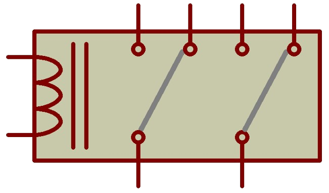
Pin Configuration and Descriptions

Pin Number Description Type
1 Coil Voltage (VCC) Input
2 Control Signal (IN) Input
3 Ground (GND) Ground
4 Normally Open (NO) Output
5 Common (COM) Output
6 Normally Closed (NC) Output

Usage Instructions

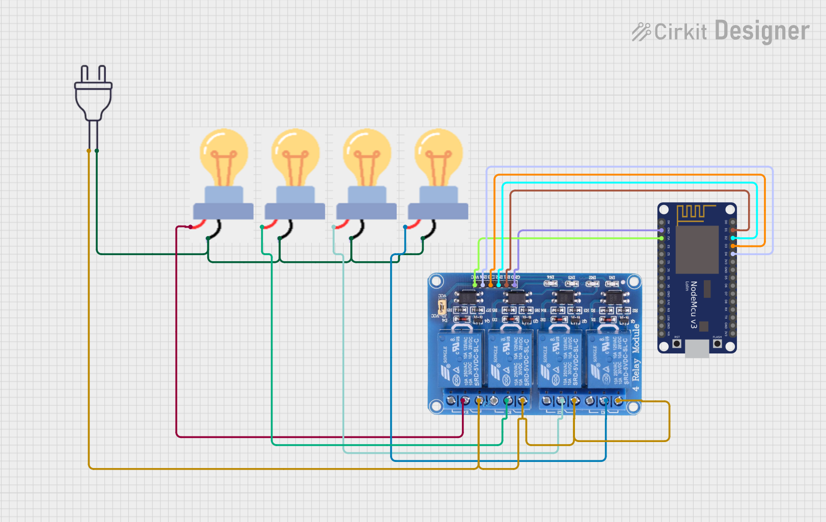
How to Use the Relay in a Circuit

  1. Connect the relay coil pins to your control circuit (VCC to positive, GND to ground).
  2. Apply the control signal to the IN pin to energize the coil.
  3. Connect the high-power circuit to the Common (COM) and either Normally Open (NO) or Normally Closed (NC) contacts depending on whether you want the circuit to be closed or open when the relay is not energized.

Important Considerations and Best Practices

  • Ensure the coil voltage matches the control signal voltage to prevent damage.
  • Do not exceed the contact rating to avoid overheating and potential failure.
  • Use a diode across the relay coil to prevent back EMF when the coil is de-energized.
  • Consider using a relay with a higher current rating than your load to ensure reliability.

Example Code for Arduino UNO

// Define relay control pin
const int relayPin = 2;

void setup() {
  // Set the relay control pin as an output
  pinMode(relayPin, OUTPUT);
}

void loop() {
  // Turn on the relay by setting the control pin LOW
  digitalWrite(relayPin, LOW);
  delay(1000); // Wait for 1 second
  
  // Turn off the relay by setting the control pin HIGH
  digitalWrite(relayPin, HIGH);
  delay(1000); // Wait for 1 second
}

Troubleshooting and FAQs

Common Issues

  • Relay does not switch: Check the control signal and coil voltage.
  • Contacts are stuck: This may be due to welding from high current. Replace the relay.
  • Intermittent operation: Verify connections and ensure there is no mechanical obstruction.

Solutions and Tips for Troubleshooting

  • If the relay coil is not energizing, check the control signal and power supply.
  • Ensure the load does not exceed the contact rating of the relay.
  • Use a multimeter to check for continuity across the relay contacts when energized.

FAQs

Q: Can I use a relay with a higher voltage rating than my load? A: Yes, it is safe to use a relay with a higher voltage rating than your load.

Q: How do I know if my relay is working? A: You can listen for a click when the relay is energized or use a multimeter to check for continuity across the contacts.

Q: Can I control a relay directly with a microcontroller? A: Yes, but ensure the coil current is within the microcontroller's drive capability, or use a transistor to amplify the signal.