How to Use DC Motor Controller: Examples, Pinouts, and Specs
Introduction
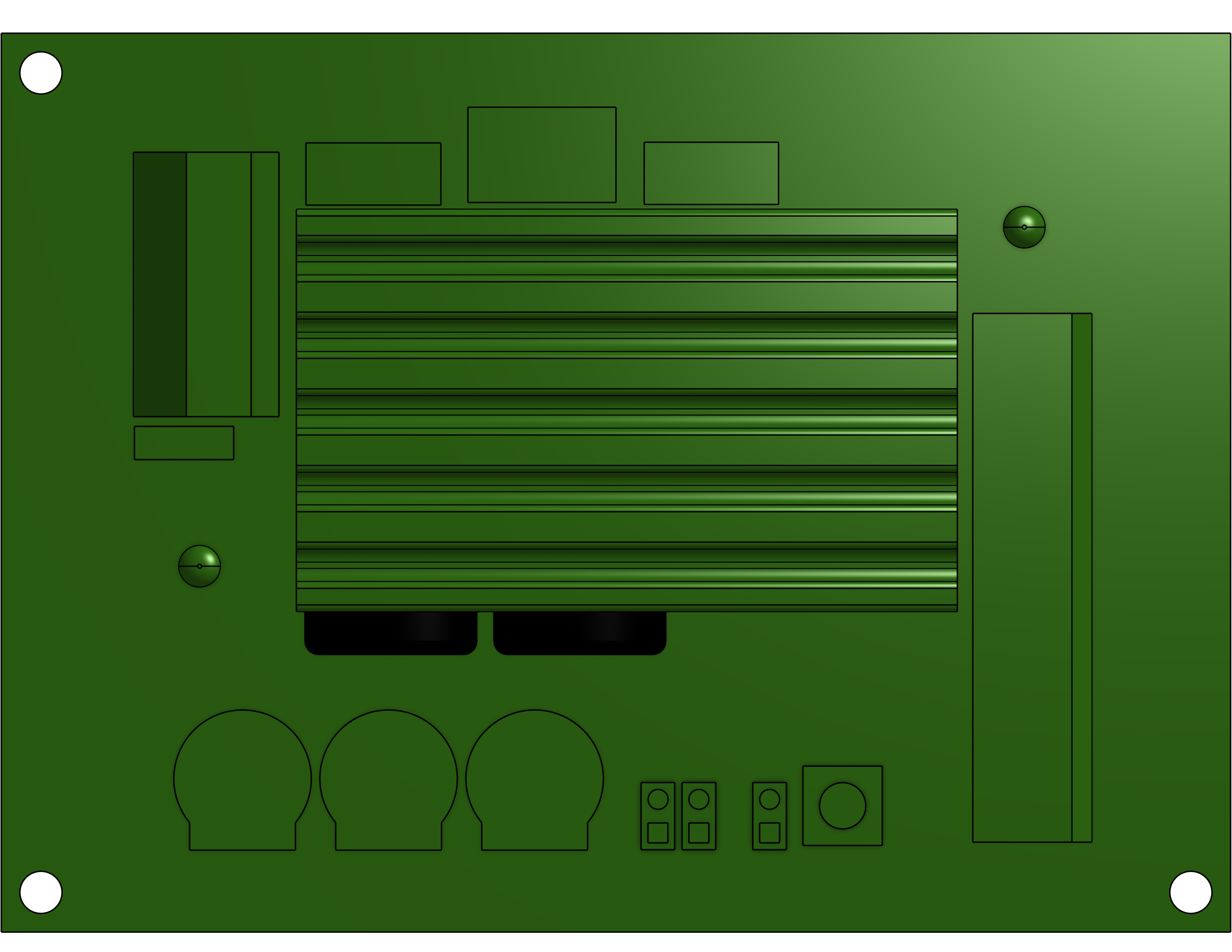
The H-Tronic DC Motor Controller (Part ID: 1191510) is a versatile device designed to regulate the speed and direction of DC motors by adjusting the voltage and current supplied to them. This controller is ideal for applications requiring precise motor control, such as robotics, conveyor systems, and automated machinery. Its robust design ensures reliable performance in both hobbyist and industrial settings.
Explore Projects Built with DC Motor Controller

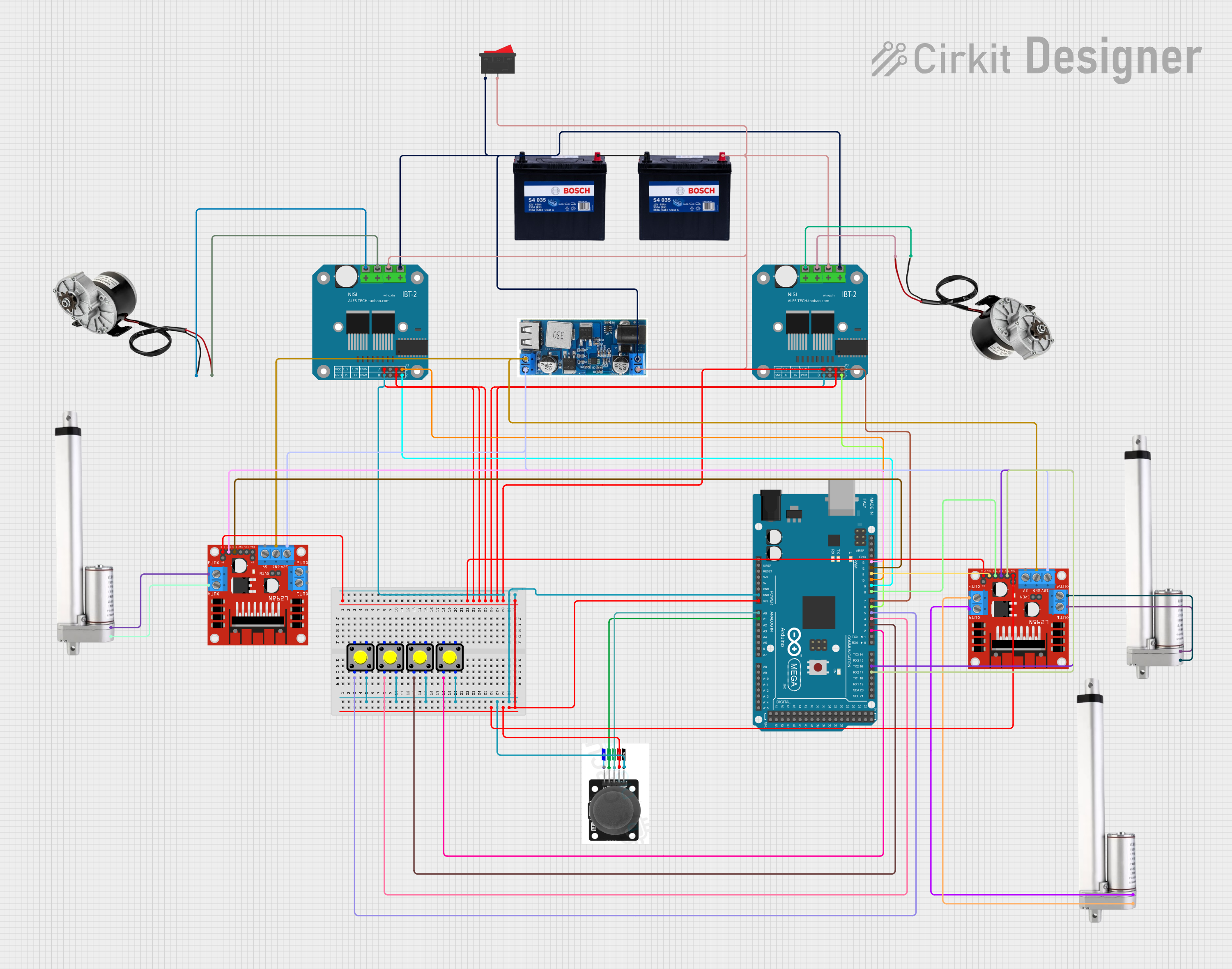
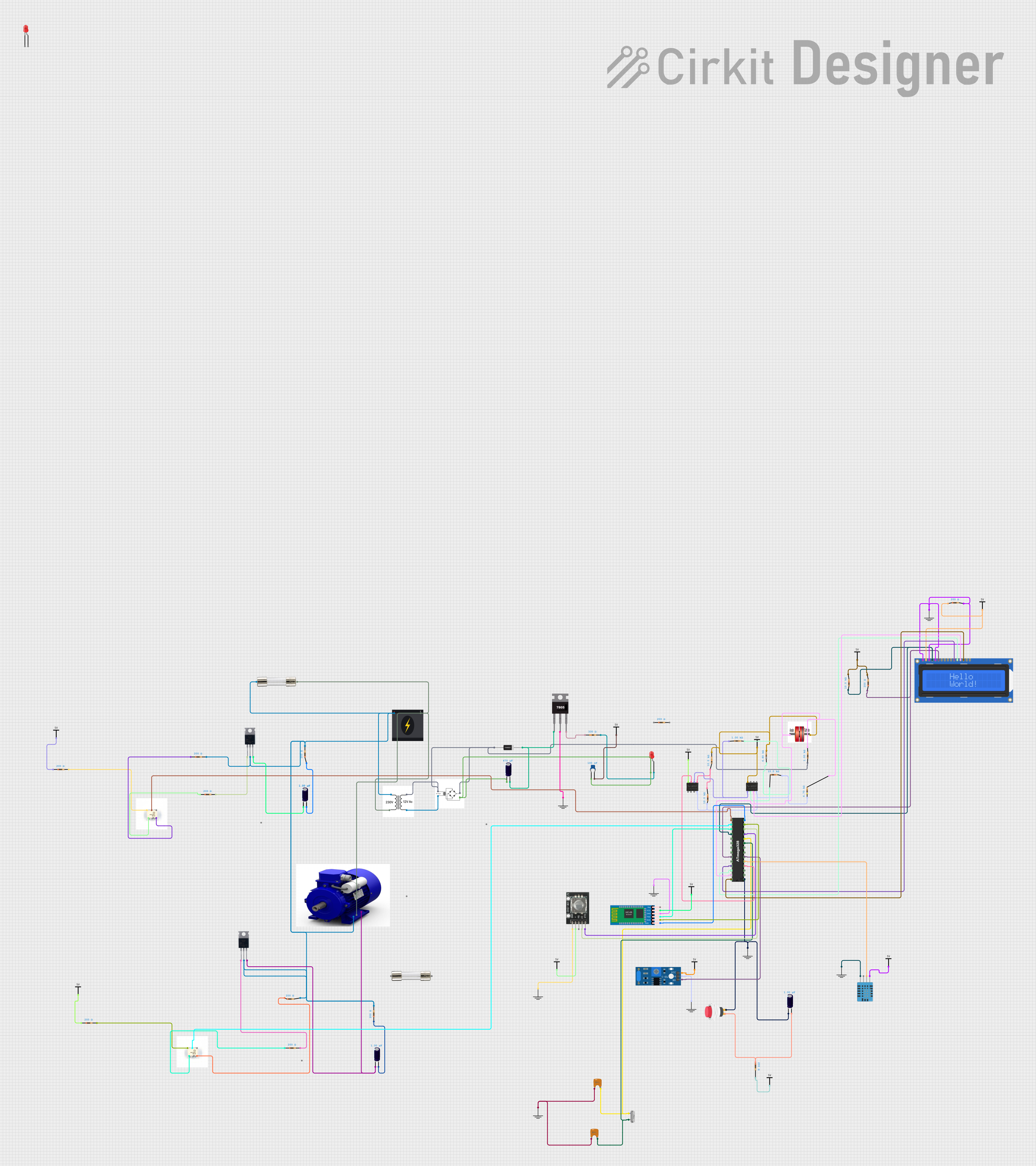
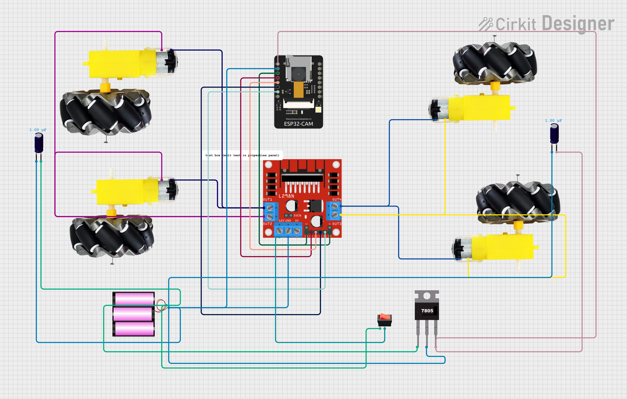
Explore Projects Built with DC Motor Controller
Common Applications
- Robotics and automation
- Conveyor belt systems
- Electric vehicles
- Fan speed control
- DIY electronics projects
Technical Specifications
The following table outlines the key technical details of the H-Tronic DC Motor Controller:
| Parameter | Value |
|---|---|
| Input Voltage Range | 6V to 24V DC |
| Output Voltage Range | 0V to 24V DC (adjustable) |
| Maximum Output Current | 5A |
| Control Method | Pulse Width Modulation (PWM) |
| PWM Frequency | 20 kHz |
| Direction Control | Forward/Reverse |
| Operating Temperature | -10°C to 50°C |
| Dimensions | 75mm x 50mm x 30mm |
Pin Configuration and Descriptions
The H-Tronic DC Motor Controller features the following pin layout:
| Pin Name | Type | Description |
|---|---|---|
| VIN+ | Power Input | Positive terminal for the input voltage (6V to 24V DC). |
| VIN- | Power Input | Negative terminal for the input voltage (ground). |
| M+ | Motor Output | Positive terminal for the DC motor connection. |
| M- | Motor Output | Negative terminal for the DC motor connection. |
| PWM | Control Input | PWM signal input for speed control (0% to 100% duty cycle). |
| DIR | Control Input | Direction control input (logic HIGH for forward, logic LOW for reverse). |
| GND | Ground | Common ground for the control signals and power supply. |
Usage Instructions
How to Use the Component in a Circuit
- Power Supply Connection: Connect the VIN+ and VIN- pins to a DC power supply within the specified voltage range (6V to 24V DC).
- Motor Connection: Attach the DC motor terminals to the M+ and M- pins. Ensure proper polarity for the desired initial direction.
- Control Signals:
- Connect a PWM signal (0V to 5V) to the PWM pin to control the motor speed. A higher duty cycle increases the speed.
- Use the DIR pin to set the motor direction. Apply a HIGH signal (5V) for forward rotation and a LOW signal (0V) for reverse rotation.
- Common Ground: Ensure that the GND pin is connected to the ground of the control circuit (e.g., microcontroller or Arduino).
Important Considerations and Best Practices
- Current Limitation: Ensure the motor's current draw does not exceed the controller's maximum output current of 5A.
- Heat Dissipation: If operating at high currents, consider adding a heat sink or active cooling to prevent overheating.
- PWM Signal: Use a PWM frequency of 20 kHz for optimal performance and to minimize audible noise.
- Reverse Polarity Protection: Double-check connections to avoid damage caused by reverse polarity.
- Decoupling Capacitors: Add decoupling capacitors near the power input to reduce voltage spikes and noise.
Example: Using with an Arduino UNO
Below is an example Arduino sketch to control the H-Tronic DC Motor Controller:
// Define pin connections
const int pwmPin = 9;  // PWM signal pin connected to Arduino pin 9
const int dirPin = 8;  // Direction control pin connected to Arduino pin 8

void setup() {
  // Set pin modes
  pinMode(pwmPin, OUTPUT);
  pinMode(dirPin, OUTPUT);
}

void loop() {
  // Set motor direction to forward
  digitalWrite(dirPin, HIGH); // Logic HIGH for forward direction

  // Gradually increase motor speed
  for (int speed = 0; speed <= 255; speed++) {
    analogWrite(pwmPin, speed); // Write PWM signal (0-255)
    delay(20); // Delay for smooth acceleration
  }

  delay(1000); // Run at full speed for 1 second

  // Gradually decrease motor speed
  for (int speed = 255; speed >= 0; speed--) {
    analogWrite(pwmPin, speed); // Write PWM signal (0-255)
    delay(20); // Delay for smooth deceleration
  }

  delay(1000); // Pause before reversing direction

  // Set motor direction to reverse
  digitalWrite(dirPin, LOW); // Logic LOW for reverse direction

  // Repeat the same speed control process in reverse
  for (int speed = 0; speed <= 255; speed++) {
    analogWrite(pwmPin, speed);
    delay(20);
  }

  delay(1000);

  for (int speed = 255; speed >= 0; speed--) {
    analogWrite(pwmPin, speed);
    delay(20);
  }

  delay(1000); // Pause before restarting the loop
}
Troubleshooting and FAQs
Common Issues and Solutions
Motor Does Not Spin:
- Verify that the power supply voltage is within the specified range (6V to 24V DC).
- Check all connections, especially the motor terminals (M+ and M-).
- Ensure the PWM signal is being correctly generated by the control circuit.
Motor Spins in the Wrong Direction:
- Reverse the logic level on the DIR pin (HIGH for forward, LOW for reverse).
- Alternatively, swap the motor connections on the M+ and M- pins.
Overheating:
- Ensure the motor's current draw does not exceed 5A.
- Add a heat sink or active cooling to the controller if necessary.
PWM Signal Not Detected:
- Confirm that the PWM signal is within the 0V to 5V range.
- Check the PWM frequency (should be 20 kHz).
FAQs
Q: Can I use this controller with a 12V DC motor?
A: Yes, the controller supports input voltages from 6V to 24V DC, making it compatible with 12V motors.
Q: What happens if the motor draws more than 5A?
A: Exceeding the maximum current rating may damage the controller. Use a motor with a current draw within the specified limit.
Q: Can I control multiple motors with one controller?
A: No, this controller is designed to drive a single DC motor. For multiple motors, use additional controllers.
Q: Is the controller compatible with other microcontrollers besides Arduino?
A: Yes, the controller can be used with any microcontroller capable of generating a PWM signal and logic-level outputs.
This concludes the documentation for the H-Tronic DC Motor Controller (Part ID: 1191510).