How to Use STA540: Examples, Pinouts, and Specs
Introduction
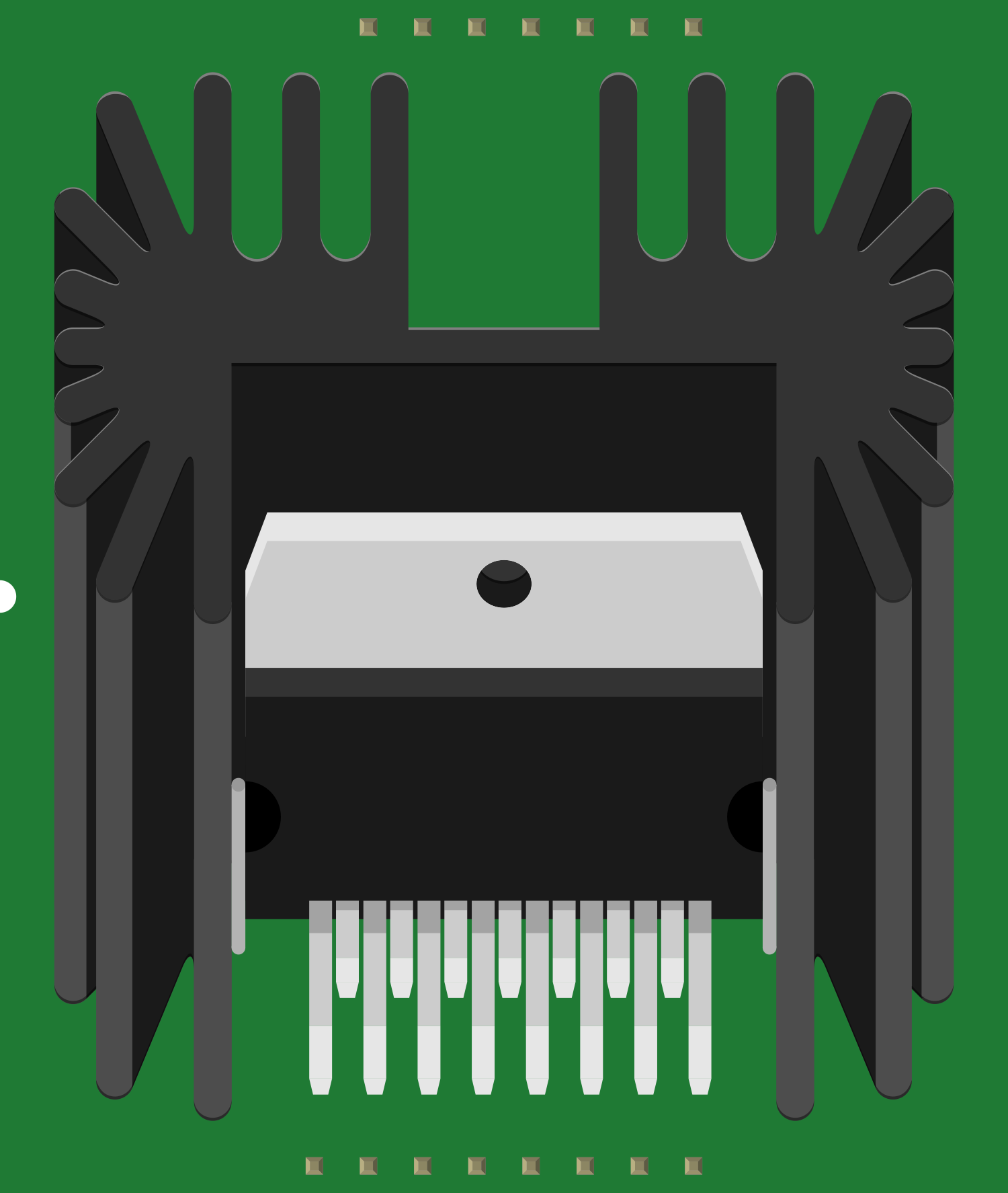
The STA540 is a versatile 4-channel audio amplifier integrated circuit (IC) capable of delivering up to 6W of continuous RMS power per channel into 4-ohm loads. With its high-quality audio performance and low distortion, the STA540 is suitable for a wide range of applications, including home stereo systems, active speakers, and other audio amplification setups.
Explore Projects Built with STA540


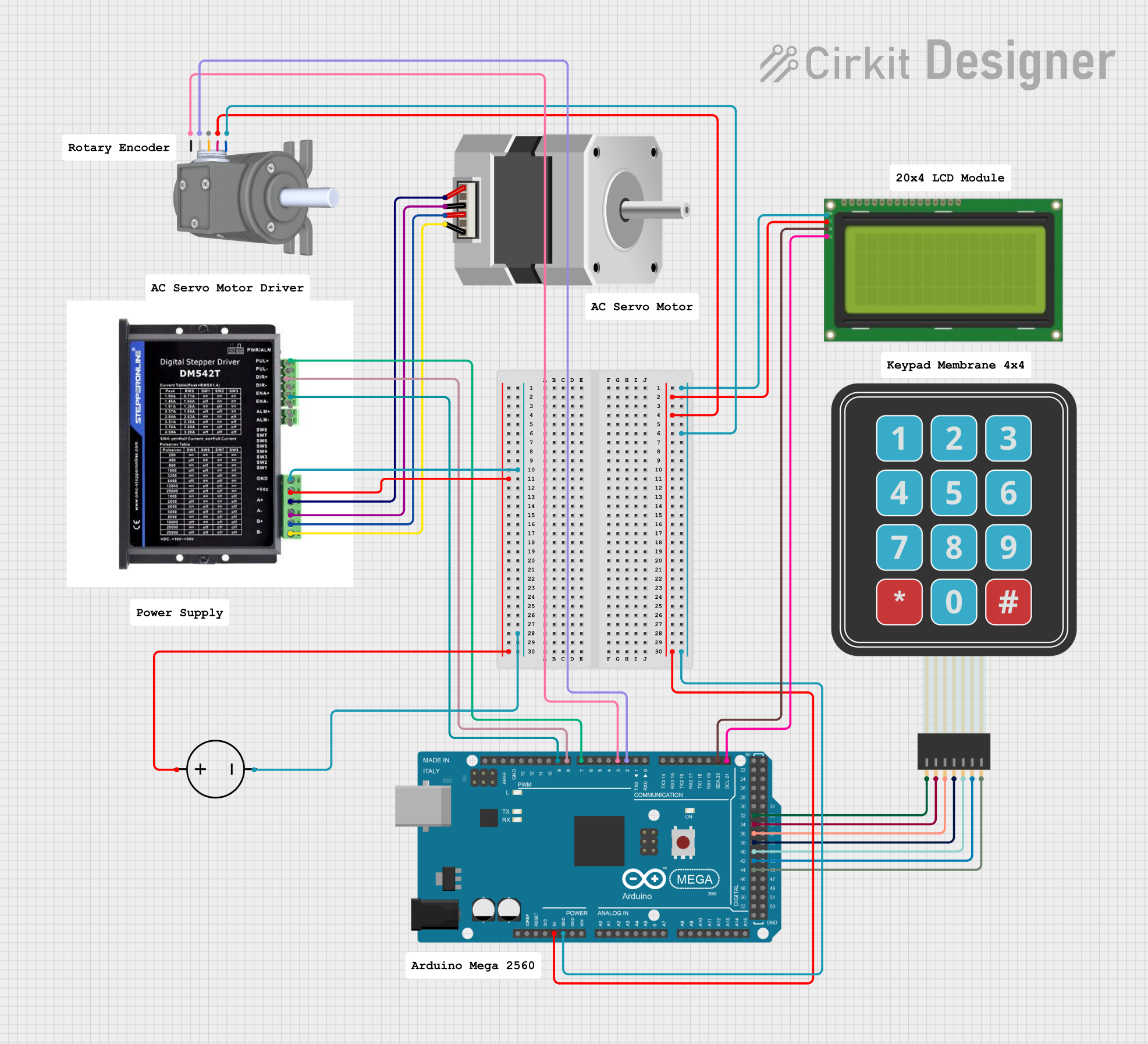

Explore Projects Built with STA540
Common Applications and Use Cases
- Home theater systems
- Multi-room audio systems
- DIY audio projects
- Active speaker designs
- Desktop audio amplifiers
Technical Specifications
Key Technical Details
- Supply Voltage (Vcc): 10V to 22V
- Output Power: Up to 6W per channel (RMS) into 4 ohms
- Total Harmonic Distortion (THD): 0.1% at 1W, 1kHz
- Signal-to-Noise Ratio (SNR): 100 dB (A-weighted)
- Frequency Response: 20Hz to 20kHz
- Number of Channels: 4
- Load Impedance: 4 ohms to 8 ohms
Pin Configuration and Descriptions
| Pin Number | Pin Name | Description |
|---|---|---|
| 1 | SVRR | Standby Voltage Right Rail |
| 2 | OUT1 | Output Channel 1 |
| 3 | Vcc | Positive Supply Voltage |
| 4 | OUT2 | Output Channel 2 |
| 5 | GND | Ground |
| 6 | OUT3 | Output Channel 3 |
| 7 | Vcc | Positive Supply Voltage |
| 8 | OUT4 | Output Channel 4 |
| 9 | SVRL | Standby Voltage Left Rail |
Usage Instructions
How to Use the STA540 in a Circuit
- Power Supply: Connect a power supply within the range of 10V to 22V to the Vcc pins (3 and 7) and ground to the GND pin (5).
- Input Signals: Connect the audio input signals to the appropriate input pins, ensuring that the signals are within the IC's acceptable range.
- Output Connections: Connect each output pin (2, 4, 6, 8) to the respective speaker, taking care to match the impedance of the speaker with the IC's specifications.
- Heat Management: Implement proper heat sinking for the IC to prevent overheating during operation.
Important Considerations and Best Practices
- Always use a power supply that matches the recommended voltage range.
- Ensure that the speakers or loads connected to the output channels match the IC's load impedance range.
- Use decoupling capacitors close to the power supply pins to minimize noise and ripple.
- Avoid short-circuiting the output pins as this can damage the IC.
- Implement proper thermal management to ensure the IC operates within its temperature range.
Troubleshooting and FAQs
Common Issues Users Might Face
- No Sound Output: Check power supply connections, input signal presence, and speaker connections.
- Distorted Sound: Ensure that the input signal level is not too high, causing clipping. Also, check for proper load impedance matching.
- Overheating: Verify that the heat sink is adequate and that the IC is not being driven beyond its specified power ratings.
Solutions and Tips for Troubleshooting
- No Sound Output: Verify that the IC is not in standby mode and that the power supply is functioning correctly.
- Distorted Sound: Adjust the input signal level or check for any damaged components in the signal path.
- Overheating: Improve heat dissipation with a larger heat sink or by improving airflow around the IC.
Example Arduino UNO Connection and Code
The STA540 can be used with an Arduino UNO to create a simple audio amplifier system. Below is an example of how to connect the STA540 to an Arduino UNO and a sample code snippet to control the volume.
Arduino UNO Connection
- Connect the Arduino 5V pin to the STA540 Vcc pins with a suitable voltage regulator in between.
- Connect the Arduino GND pin to the STA540 GND pin.
- Connect a PWM output pin from the Arduino to the input of the STA540 for volume control.
Sample Arduino Code
// Define the PWM pin connected to the STA540 input
const int audioInputPin = 9;

void setup() {
  // Set the PWM pin as an output
  pinMode(audioInputPin, OUTPUT);
}

void loop() {
  // Generate a simple tone by toggling the PWM pin
  analogWrite(audioInputPin, 128); // Set volume to 50%
  delay(1000); // Play tone for 1 second
  analogWrite(audioInputPin, 0); // Mute
  delay(1000); // Pause for 1 second
}
Note: This code is a basic example to demonstrate controlling the volume of the STA540 using PWM. For actual audio input, an external DAC or audio source should be used.
Remember to consult the STA540 datasheet for more detailed information and to ensure proper usage and handling of the IC.