How to Use BMI270: Examples, Pinouts, and Specs
Introduction
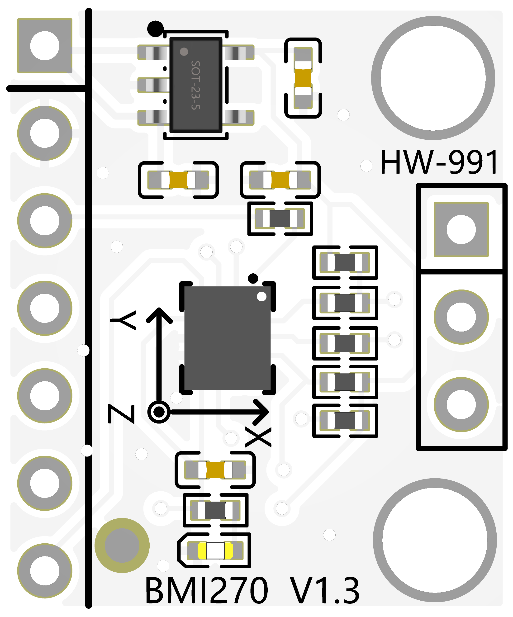
The BMI270 is a low-power, 6-axis inertial measurement unit (IMU) manufactured by 宏维微 (Part ID: HW-991). It integrates a 3-axis accelerometer and a 3-axis gyroscope into a single compact package. This component is designed for motion sensing applications, offering high accuracy and low power consumption. Its advanced features make it particularly suitable for wearable devices, fitness trackers, augmented reality (AR) systems, and Internet of Things (IoT) applications.
Explore Projects Built with BMI270
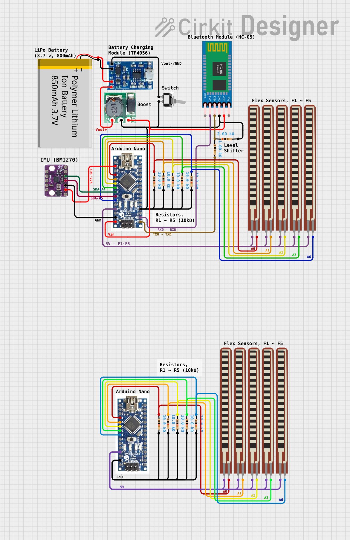
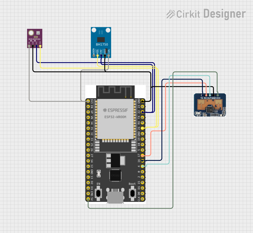

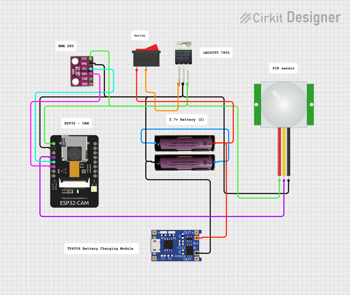
Explore Projects Built with BMI270
Common Applications
- Wearable devices (e.g., fitness trackers, smartwatches)
- IoT motion sensing
- Augmented reality (AR) and virtual reality (VR) systems
- Robotics and drone stabilization
- Gesture recognition systems
Technical Specifications
Key Technical Details
| Parameter | Value |
|---|---|
| Manufacturer | 宏维微 |
| Part ID | HW-991 |
| Sensor Type | 6-axis IMU (3-axis accelerometer + 3-axis gyroscope) |
| Operating Voltage | 1.71V to 3.6V |
| Current Consumption | 30 µA (low-power mode) |
| Accelerometer Range | ±2g, ±4g, ±8g, ±16g |
| Gyroscope Range | ±125°/s, ±250°/s, ±500°/s, ±1000°/s, ±2000°/s |
| Communication Interface | I²C, SPI |
| Operating Temperature Range | -40°C to +85°C |
| Package Type | LGA-14 (2.5 mm x 3.0 mm x 0.8 mm) |
Pin Configuration and Descriptions
The BMI270 comes in a 14-pin LGA package. Below is the pin configuration:
| Pin Number | Pin Name | Description |
|---|---|---|
| 1 | VDD | Power supply (1.71V to 3.6V) |
| 2 | VDDIO | I/O voltage supply |
| 3 | GND | Ground |
| 4 | CS | Chip select (SPI mode) |
| 5 | SDO | Serial data output (SPI mode) |
| 6 | SDA/SDI | Data line for I²C or SPI |
| 7 | SCL/SCK | Clock line for I²C or SPI |
| 8 | INT1 | Interrupt 1 output |
| 9 | INT2 | Interrupt 2 output |
| 10 | NC | Not connected |
| 11 | NC | Not connected |
| 12 | NC | Not connected |
| 13 | NC | Not connected |
| 14 | NC | Not connected |
Usage Instructions
How to Use the BMI270 in a Circuit
- Power Supply: Connect the VDD pin to a stable power source (1.71V to 3.6V). Use a decoupling capacitor (e.g., 0.1 µF) close to the VDD pin to reduce noise.
- Communication Interface: Choose between I²C or SPI communication:
- For I²C, connect the SDA and SCL pins to the corresponding I²C lines on your microcontroller. Pull-up resistors (typically 4.7 kΩ) are required on both lines.
- For SPI, connect CS, SDO, SDI, and SCK to the corresponding SPI lines on your microcontroller.
- Interrupts: Use the INT1 and INT2 pins to handle motion-triggered interrupts if needed.
- Initialization: Configure the BMI270 using the appropriate register settings for your application (e.g., accelerometer range, gyroscope range, and output data rate).
Important Considerations
- Power Modes: The BMI270 supports multiple power modes (e.g., normal, low-power). Select the appropriate mode to balance power consumption and performance.
- Mounting Orientation: Ensure the sensor is mounted correctly to align with the desired axes of motion.
- I²C Address: The default I²C address is
0x68. If the AD0 pin is pulled high, the address changes to0x69.
Example Code for Arduino UNO
Below is an example of how to interface the BMI270 with an Arduino UNO using I²C communication:
#include <Wire.h>

#define BMI270_I2C_ADDRESS 0x68 // Default I²C address of the BMI270

void setup() {
  Wire.begin(); // Initialize I²C communication
  Serial.begin(9600); // Initialize serial communication for debugging

  // Initialize BMI270
  Wire.beginTransmission(BMI270_I2C_ADDRESS);
  Wire.write(0x7E); // Register address for command register
  Wire.write(0x11); // Command to initialize accelerometer and gyroscope
  Wire.endTransmission();

  Serial.println("BMI270 initialized.");
}

void loop() {
  // Read accelerometer data
  Wire.beginTransmission(BMI270_I2C_ADDRESS);
  Wire.write(0x12); // Register address for accelerometer data
  Wire.endTransmission();
  Wire.requestFrom(BMI270_I2C_ADDRESS, 6); // Request 6 bytes (X, Y, Z)

  if (Wire.available() == 6) {
    int16_t accelX = (Wire.read() | (Wire.read() << 8));
    int16_t accelY = (Wire.read() | (Wire.read() << 8));
    int16_t accelZ = (Wire.read() | (Wire.read() << 8));

    Serial.print("Accel X: "); Serial.print(accelX);
    Serial.print(" Y: "); Serial.print(accelY);
    Serial.print(" Z: "); Serial.println(accelZ);
  }

  delay(500); // Delay for readability
}
Troubleshooting and FAQs
Common Issues
No Communication with the Sensor:
- Ensure the correct I²C address (
0x68or0x69) is being used. - Verify pull-up resistors are connected to the SDA and SCL lines.
- Check for loose or incorrect wiring.
- Ensure the correct I²C address (
Incorrect or No Data Output:
- Confirm that the sensor is properly initialized (e.g., accelerometer and gyroscope are enabled).
- Verify the power supply voltage is within the specified range (1.71V to 3.6V).
High Power Consumption:
- Ensure the sensor is operating in the desired power mode (e.g., low-power mode for battery-operated devices).
Tips for Troubleshooting
- Use an oscilloscope or logic analyzer to monitor I²C or SPI signals for debugging communication issues.
- Check the interrupt pins (INT1, INT2) to verify if motion events are being triggered as expected.
- Refer to the BMI270 datasheet for detailed register descriptions and configuration options.
This documentation provides a comprehensive guide to understanding and using the BMI270 IMU. For further details, consult the official datasheet or contact the manufacturer, 宏维微.