How to Use Stepdown 5V: Examples, Pinouts, and Specs
Introduction
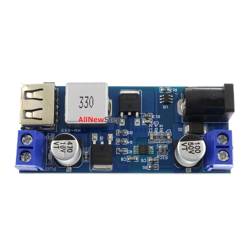
A Stepdown 5V converter, also known as a buck converter, is an electronic component designed to reduce a higher input voltage to a stable 5V output. This component is widely used in power supply circuits to provide a reliable 5V source for powering microcontrollers, sensors, and other electronic devices. Its efficiency and compact design make it an essential component in battery-powered systems, embedded devices, and portable electronics.
Explore Projects Built with Stepdown 5V


Explore Projects Built with Stepdown 5V
Common Applications and Use Cases
- Powering microcontrollers like Arduino, Raspberry Pi, and ESP32.
- Supplying 5V to sensors, modules, and peripherals in embedded systems.
- Converting 12V or 24V from batteries or adapters to 5V for USB-powered devices.
- Used in automotive electronics to step down the car battery voltage to 5V.
Technical Specifications
Below are the key technical details of the Stepdown 5V converter:
| Parameter | Value |
|---|---|
| Input Voltage Range | 6V to 24V |
| Output Voltage | 5V (regulated) |
| Output Current | Up to 3A (depending on the model) |
| Efficiency | Up to 95% |
| Switching Frequency | 150 kHz to 1 MHz |
| Operating Temperature | -40°C to +85°C |
| Dimensions | Varies (e.g., 22mm x 17mm x 4mm) |
Pin Configuration and Descriptions
The Stepdown 5V converter typically has the following pin configuration:
| Pin Name | Description |
|---|---|
| VIN | Input voltage pin. Connect the higher input voltage (e.g., 12V or 24V) here. |
| GND | Ground pin. Connect to the ground of the power source and the load circuit. |
| VOUT | Output voltage pin. Provides a stable 5V output to power the load. |
| EN (optional) | Enable pin. Used to turn the converter on/off. Active high (connect to VIN to enable). |
Usage Instructions
How to Use the Stepdown 5V Converter in a Circuit
Connect the Input Voltage (VIN):
- Connect the positive terminal of the input power source (e.g., a 12V battery) to the VIN pin.
- Ensure the input voltage is within the specified range (6V to 24V).
Connect the Ground (GND):
- Connect the ground of the input power source and the load circuit to the GND pin.
Connect the Output Voltage (VOUT):
- Connect the VOUT pin to the device or circuit that requires a 5V power supply.
Optional - Enable Pin (EN):
- If the converter has an EN pin, connect it to VIN to enable the output. Leave it unconnected or pull it low to disable the converter.
Add Decoupling Capacitors:
- Place a capacitor (e.g., 10µF) between VIN and GND, and another between VOUT and GND, to improve stability and reduce noise.
Verify Connections:
- Double-check all connections before powering the circuit to avoid damage to the converter or connected devices.
Important Considerations and Best Practices
- Input Voltage Range: Ensure the input voltage is within the specified range to prevent damage to the converter.
- Heat Dissipation: For high current loads, the converter may generate heat. Use a heatsink or ensure proper ventilation if necessary.
- Load Current: Do not exceed the maximum output current rating (e.g., 3A) to avoid overloading the converter.
- Polarity Protection: Double-check the polarity of the input voltage to prevent damage to the component.
Example: Using the Stepdown 5V Converter with an Arduino UNO
The Stepdown 5V converter can be used to power an Arduino UNO from a 12V battery. Below is an example circuit and Arduino code:
Circuit Connections
- Connect the 12V battery's positive terminal to the VIN pin of the converter.
- Connect the 12V battery's ground to the GND pin of the converter.
- Connect the VOUT pin of the converter to the 5V pin of the Arduino UNO.
- Connect the GND pin of the converter to the GND pin of the Arduino UNO.
Arduino Code Example
// Example code to blink an LED connected to pin 13 of the Arduino UNO
// Ensure the Arduino is powered via the Stepdown 5V converter

void setup() {
  pinMode(13, OUTPUT); // Set pin 13 as an output pin
}

void loop() {
  digitalWrite(13, HIGH); // Turn the LED on
  delay(1000);            // Wait for 1 second
  digitalWrite(13, LOW);  // Turn the LED off
  delay(1000);            // Wait for 1 second
}
Troubleshooting and FAQs
Common Issues and Solutions
No Output Voltage:
- Cause: Input voltage is too low or not connected properly.
- Solution: Verify the input voltage is within the specified range and check the connections.
Overheating:
- Cause: Excessive load current or poor ventilation.
- Solution: Reduce the load current or add a heatsink to the converter.
Output Voltage is Unstable:
- Cause: Insufficient decoupling capacitors or noisy input power.
- Solution: Add capacitors (e.g., 10µF or 100µF) between VIN and GND, and VOUT and GND.
Converter Not Turning On:
- Cause: EN pin is not connected or pulled low.
- Solution: Connect the EN pin to VIN to enable the converter.
FAQs
Q: Can I use the Stepdown 5V converter to power USB devices?
A: Yes, as long as the device's current requirement does not exceed the converter's maximum output current.
Q: What happens if I exceed the input voltage range?
A: Exceeding the input voltage range can damage the converter. Always ensure the input voltage is within the specified range.
Q: Can I use this converter with a solar panel?
A: Yes, but ensure the solar panel's output voltage is within the converter's input range, and use capacitors to stabilize the input voltage.
Q: Is the output voltage adjustable?
A: Some Stepdown 5V converters have an adjustable output. Check the specific model's datasheet for details.