How to Use Adafruit LIS331: Examples, Pinouts, and Specs
Introduction
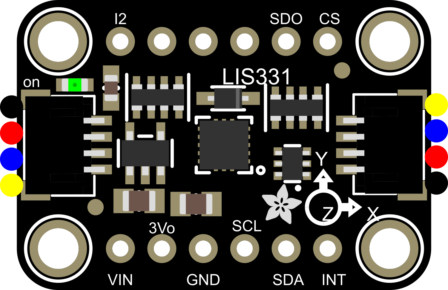
The Adafruit LIS331 is a high-performance 3-axis accelerometer that provides digital acceleration measurements in three dimensions: X, Y, and Z. This compact and low-power module is capable of detecting motion, tilt, and vibration with high precision. It is commonly used in applications such as gaming controllers, robotics, vehicle dynamics, and any system that requires motion monitoring or inertial measurements.
Explore Projects Built with Adafruit LIS331
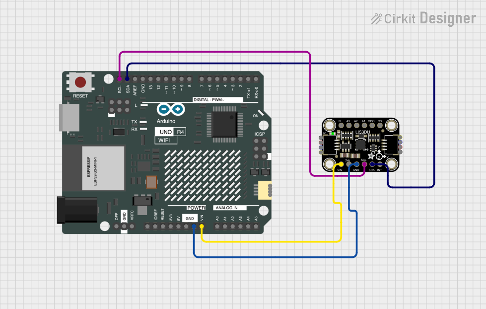
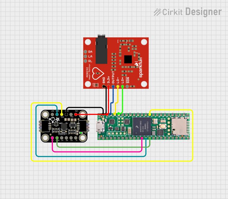

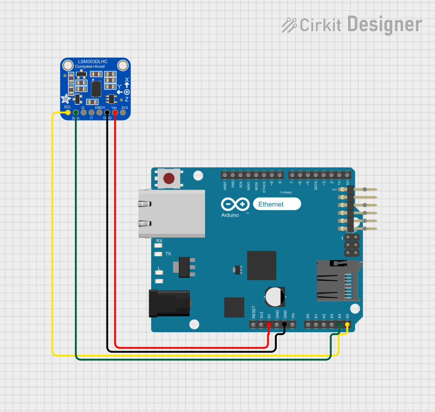
Explore Projects Built with Adafruit LIS331
Common Applications and Use Cases
- Motion detection and tracking
- Tilt sensing in remote controls or handheld devices
- Vibration monitoring in machinery
- Inertial measurement units (IMUs) for navigation systems
- Activity monitoring in wearable devices
Technical Specifications
Key Technical Details
- Supply Voltage (Vdd): 2.16V to 3.6V
- Output Signal: Digital I2C
- Measurement Range Options: ±24g, ±48g, ±96g, ±192g
- Sensitivity: 0.73 mg/digit (±24g range)
- Data Rate Options: 0.5 Hz to 1 kHz
- Operating Temperature Range: -40°C to +85°C
Pin Configuration and Descriptions
| Pin Number | Name | Description |
|---|---|---|
| 1 | VDD | Power supply (2.16V to 3.6V) |
| 2 | GND | Ground connection |
| 3 | SCL | I2C clock line |
| 4 | SDA | I2C data line |
| 5 | INT1 | Interrupt 1 (configurable) |
| 6 | INT2 | Interrupt 2 (configurable) |
| 7 | CS | Chip select for SPI interface (if used) |
Usage Instructions
How to Use the Component in a Circuit
Power Connections: Connect the VDD pin to a power supply within the specified voltage range and the GND pin to the ground.
I2C Communication: Connect the SCL and SDA pins to the corresponding I2C clock and data lines on your microcontroller. If using an Arduino UNO, SCL connects to A5 and SDA to A4.
Interrupts (Optional): The INT1 and INT2 pins can be configured to output interrupt signals for certain events (e.g., motion detection). Connect these to digital pins on your microcontroller if this functionality is required.
SPI Interface (Optional): If using SPI communication, connect the CS pin to a digital pin on your microcontroller for chip select functionality.
Important Considerations and Best Practices
- Ensure that the power supply voltage does not exceed the maximum rating to prevent damage to the module.
- Use pull-up resistors on the I2C lines if they are not already present on your microcontroller board.
- When placing the accelerometer in your design, ensure that it is mounted securely and that the axes are aligned according to your application's requirements.
- For accurate measurements, calibrate the accelerometer in your application's environment.
Example Code for Arduino UNO
#include <Wire.h>

// Adafruit LIS331 I2C address (default is 0x19 if SA0 is high)
#define ACCEL_ADDRESS 0x19

void setup() {
  Wire.begin(); // Initialize I2C
  Serial.begin(9600); // Start serial for output

  // Setup the accelerometer
  Wire.beginTransmission(ACCEL_ADDRESS);
  Wire.write(0x20); // CTRL_REG1
  Wire.write(0x27); // Normal power mode, 50 Hz data rate
  Wire.endTransmission();
}

void loop() {
  int x, y, z;

  // Read the accelerometer
  Wire.beginTransmission(ACCEL_ADDRESS);
  Wire.write(0x28 | 0x80); // Start reading at OUT_X_L with auto-increment
  Wire.endTransmission();
  Wire.requestFrom(ACCEL_ADDRESS, 6); // Request 6 bytes (2 for each axis)

  if (Wire.available() == 6) {
    x = Wire.read() | (Wire.read() << 8);
    y = Wire.read() | (Wire.read() << 8);
    z = Wire.read() | (Wire.read() << 8);
  }

  // Output the results
  Serial.print("X: ");
  Serial.print(x);
  Serial.print(" Y: ");
  Serial.print(y);
  Serial.print(" Z: ");
  Serial.println(z);

  delay(100); // Wait for 100 milliseconds
}
Troubleshooting and FAQs
Common Issues Users Might Face
- No Data from the Accelerometer: Ensure that the I2C connections are correct and secure. Check that the correct I2C address is being used in the code.
- Inaccurate Readings: Verify that the accelerometer is properly calibrated and that there is no mechanical stress affecting the sensor.
- Intermittent Communication: Check for loose connections and ensure that pull-up resistors are installed if necessary.
Solutions and Tips for Troubleshooting
- Double-check wiring against the pin configuration table.
- Use I2C scanner code to confirm the device address.
- Ensure that the accelerometer is not subjected to forces beyond its measurement range.
- If using interrupts, ensure that the interrupt pins are correctly configured in both the module and the microcontroller.
FAQs
Q: Can the Adafruit LIS331 be used with a 5V microcontroller? A: Yes, but a level shifter is recommended for the I2C lines to ensure compatibility with the module's voltage levels.
Q: How can I change the measurement range? A: The measurement range can be set by configuring the appropriate control registers. Refer to the LIS331 datasheet for detailed instructions.
Q: What is the purpose of the CS pin? A: The CS pin is used for chip select when the module is operated in SPI mode. It is not used in I2C mode.
Q: How do I interpret the raw data from the accelerometer? A: The raw data needs to be converted into units of g-force. This involves reading the sensitivity level from the datasheet and applying the appropriate conversion factor based on the selected measurement range.